Vibration reducing and pressure bearing damping structure for blade root platform of movable blades

A technology of damping structure and moving blades, which is applied in the direction of supporting elements of blades, engine components, machines/engines, etc., can solve the problems of increasing the centrifugal force of the blades, the limitation of the structure size of the pressure damping block on the contact surface, etc., to reduce the vibration of the blades, The effect of reducing bearing pressure and improving blade strength performance

Inactive Publication Date: 2015-12-16
XI AN JIAOTONG UNIV
View PDF6 Cites 5 Cited by
  • Summary
  • Abstract
  • Description
  • Claims
  • Application Information

AI Technical Summary

Problems solved by technology

The general measure is to add a wedge-shaped damping block at the blade root platform. The damping block contacts the blade root platform under the action of centrifugal force to reduce vibration, but the damping block will increase the centrifugal force of the blade, and the pressure on the contact surface is limited by the structural size of the damping block. limit

Method used


Image

  • Vibration reducing and pressure bearing damping structure for blade root platform of movable blades
  • Vibration reducing and pressure bearing damping structure for blade root platform of movable blades
  • Vibration reducing and pressure bearing damping structure for blade root platform of movable blades

Examples


Embodiment Construction

[0020] Taking the fir tree type blade root as an example below, the present invention will be further described in conjunction with the accompanying drawings.

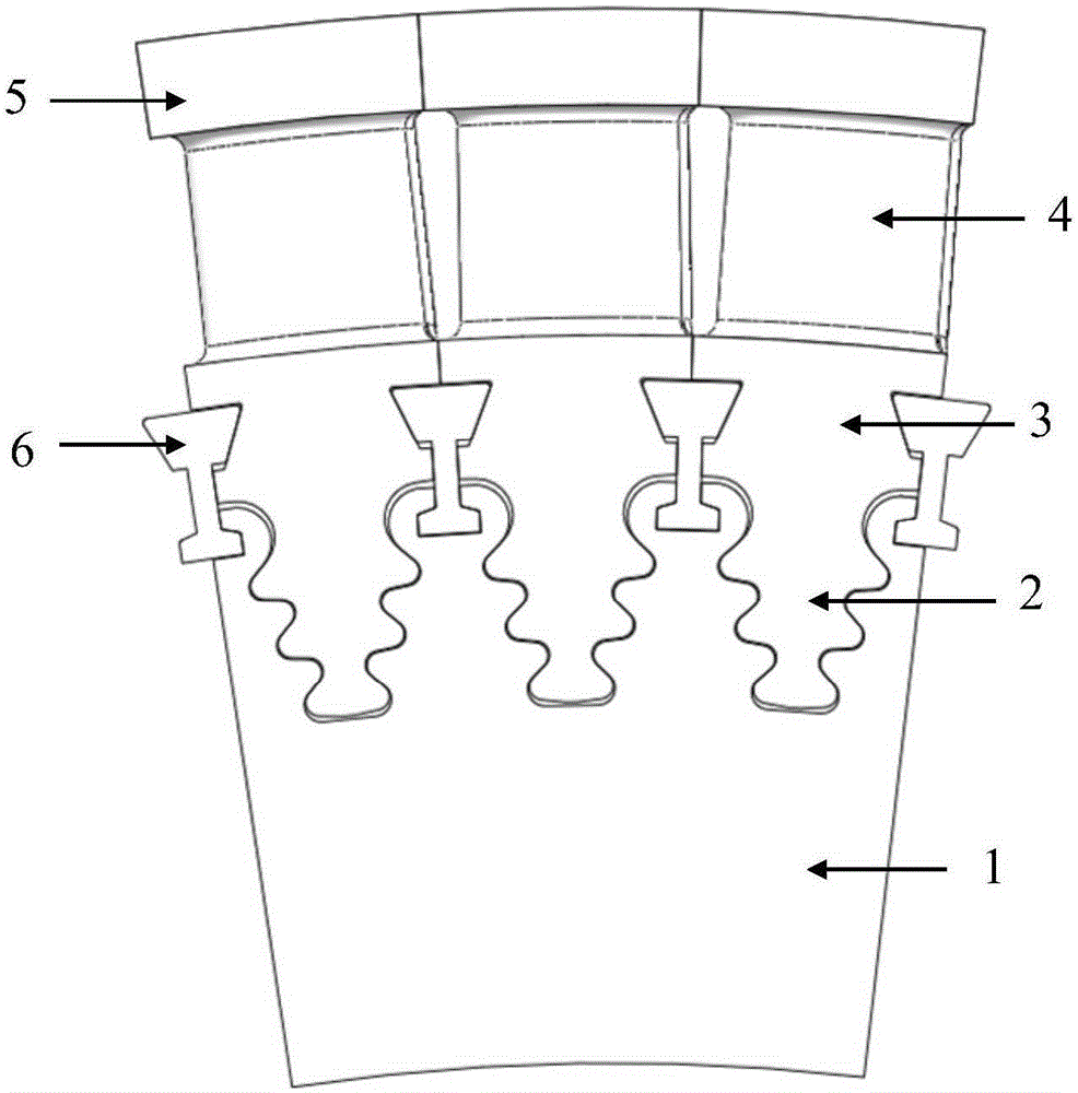
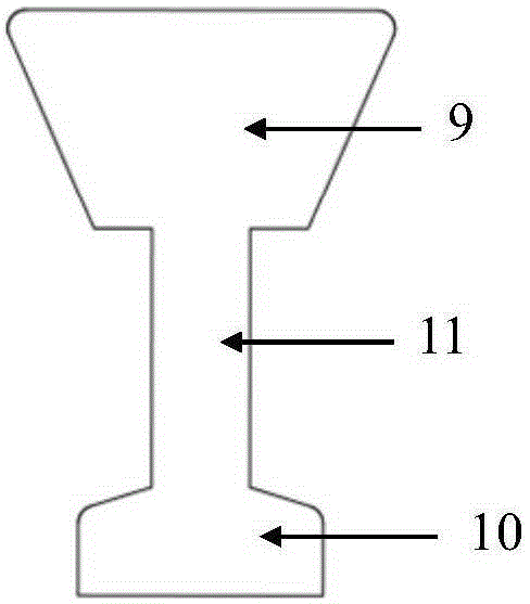
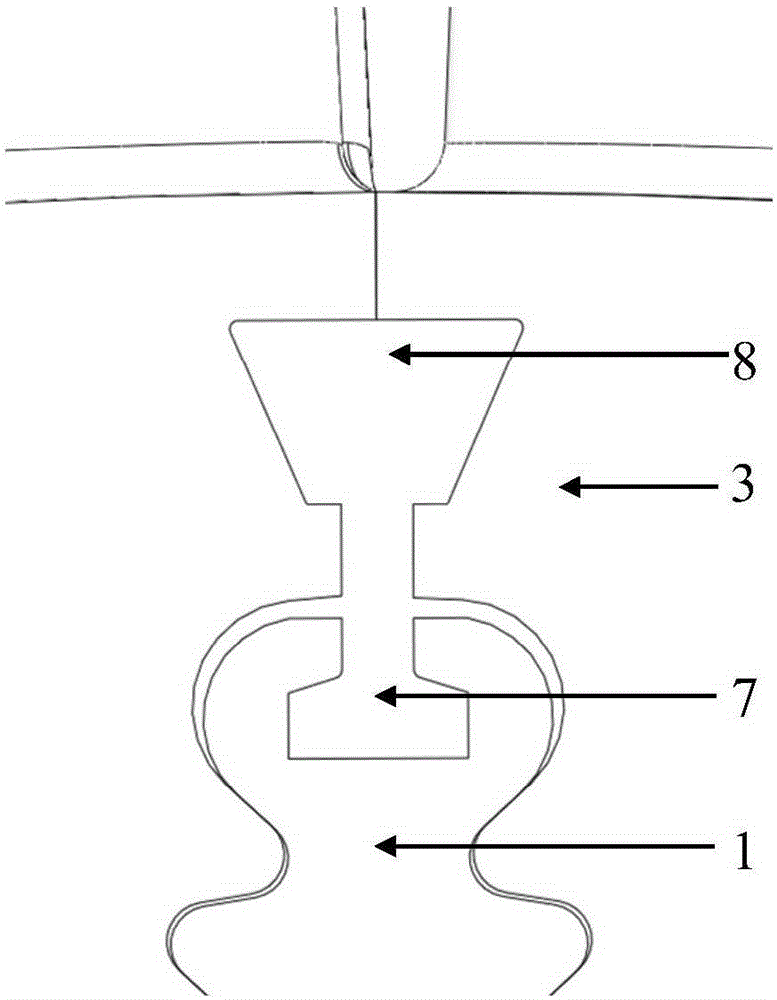
[0021] see figure 1 , the present invention is a moving blade root platform vibration damping bearing pressure damping structure, including impeller 1, moving blades and a number of damping blocks 6. Wherein, the shroud 5 is arranged on the blade body 4 of the moving blade, the blade root 2 of the moving blade is installed on the impeller 1, and several matching impeller grooves 7 and 3 are provided on the impeller 1 and the blade root platform 3 of the moving blade The size of the blade root platform groove 8, the impeller groove 7 and the blade root platform groove 8 needs to comprehensively consider the intensity and vibration level of the impeller 1 and the blade root platform 3, each impeller groove 7 and the corresponding blade root platform groove 8 all form a mounting groove, and several damping blocks 6 are i...


PUM


Abstract

The invention discloses a vibration reducing and pressure bearing damping structure for a blade root platform of movable blades. The vibration reducing and pressure bearing damping structure for the blade root platform of the movable blades comprises an impeller, the movable blades and a plurality of damping blocks. The blade roots of the movable blades are mounted on the impeller. A plurality of impeller grooves and a plurality of blade root platform grooves matched with the impeller grooves are formed in the impeller and the blade root platform of the movable blades respectively. Each impeller groove and the corresponding blade root platform groove form an installation groove. The multiple damping blocks are sequentially mounted in the corresponding installation grooves. During operation, the damping blocks make close contact with the blade root platform, so that dry friction damping is formed; when the blades are subjected to shock excitation under the action of airflow force, the damping blocks move relative to the contact surfaces between the damping blocks and the blade root platform, so that dry friction force is generated, the vibration level of the blade root platform is reduced, and vibration reducing effect is achieved. Meanwhile, not only all teeth of the impeller make contact with the blade roots to bear the centrifugal force of the blades, but also the damping blocks make contact with the blade root platform to share the centrifugal force of the blades. The vibration reducing and pressure bearing damping structure for the blade root platform of the movable blades is simple, convenient to assemble and disassemble, and capable of effectively increasing the damping of the blade root platform, reducing the vibration of the blades and improving the safety stability of a unit.

Description

Technical field: [0001] The invention relates to a steam turbine moving blade, in particular to a vibration-reducing, pressure-bearing and damping structure of the root platform of the moving blade. Background technique: [0002] The steam turbine blade is a key component of the steam turbine. Its function is to convert the thermal energy of the working medium with high temperature and high pressure into mechanical energy, which is very important for the safe operation of the steam turbine. The blades of the steam turbine are heavily loaded, the working environment is relatively harsh, and the teeth of the blade root bear a relatively high pressure. The blades are prone to vibration under the action of the excitation force of the airflow and the deviation of manufacturing and installation. Reducing the bearing pressure of the blade root and the vibration level of the blade is very important to ensure the safe and reliable operation of the whole machine. [0003] In the desi...

Claims


Application Information

Patent Timeline
Patent Type & Authority Applications(China)
IPC IPC(8): F01D5/26F01D5/30
Inventor 张荻赵伟袁瑞山谢永慧
Owner XI AN JIAOTONG UNIV
Why Eureka
Try Eureka