Low-temperature ball valve of pre-tightening sliding valve seat structure

A sliding valve and ball valve technology, applied in valve devices, engine components, cocks including cut-off devices, etc., can solve problems such as hindering the rotation of the ball, pressure imbalance, affecting the sealing effect, etc., to reduce the conveying speed and the opening force. , the effect of easy maintenance

Active Publication Date: 2015-12-16
KAIFENG RUIKE VALVE
View PDF8 Cites 3 Cited by
  • Summary
  • Abstract
  • Description
  • Claims
  • Application Information

AI Technical Summary

Problems solved by technology

The above structure has the following defects: 1. Since the valve seat assembly is only provided on both sides of the valve body, the valve seat assembly is provided with an integrated sealing ring to seal between the ball and the valve body, and the valve stem is frequently operated to drive The rotation of the sphere will damage the friction between the sealing ring and the sphere, and the friction between the sealing ring and the inner wall of the valve is relatively small. It is not necessary to replace the part of the sealing ring that is in contact with the inner wall of the valve, but the entire sealing ring is actually replaced. 2. The through hole inside the ball is a straight hole. When the ball valve is working, the medium flows quickly in the through hole of the ball. When the valve stem is turned to close the ball valve, the fast flowing medium The medium produces a large resistance to the rotation of the ball, which requires a large opening force, especially at low temperature, the working state of the ball valve will be affected and easily damaged; 3. The valve stem will contact the spring during the rotation process. The friction of the pressure plate makes the central hole of the spring pressure plate larger. When there is a large gap between the spring pressure plate and the valve stem, the pressure of the spring on the spring pressure plate on the valve stem is not evenly distributed along the circumference, so that The two sides of the spring pressure plate produce asymmetric pressure on the valve seat assembly, which makes the pressure between the valve seat assembly on both sides and the ball unbalanced. Over time, the ball will shift, affecting the sealing effect and causing medium leakage.

Method used


Image

  • Low-temperature ball valve of pre-tightening sliding valve seat structure
  • Low-temperature ball valve of pre-tightening sliding valve seat structure
  • Low-temperature ball valve of pre-tightening sliding valve seat structure

Examples


Embodiment Construction

[0018] Below in conjunction with accompanying drawing, specific embodiment of the present invention is described in further detail:

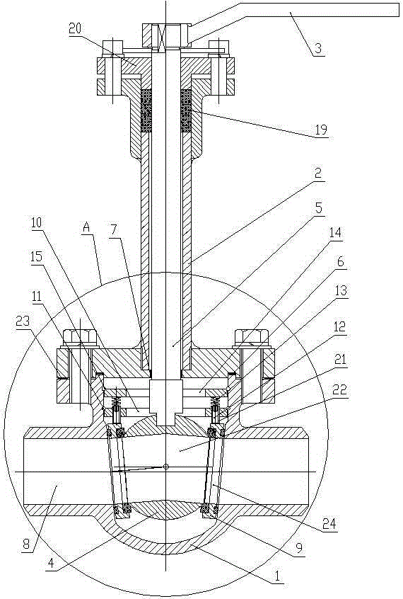
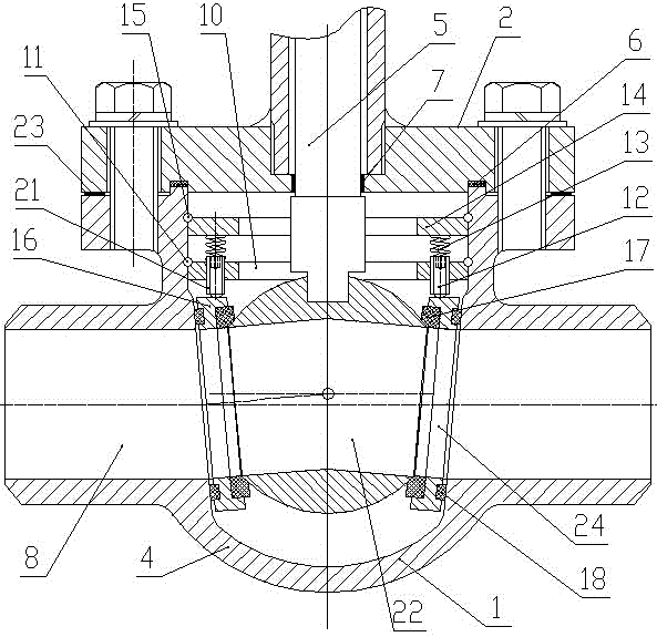
[0019] Such as figure 1 and figure 2As shown, the cryogenic ball valve with a pre-tightened sliding seat structure includes a valve body 1, a long-necked bonnet 2, a handle 3, a ball 4 and a valve stem 5. The top of the valve body 1 is open and connected to the lower end of the long-necked bonnet 2. The connection surface between the valve body 1 and the long-necked bonnet 2 is provided with a sealing ring 6, the interior of the valve body 1 is hollow and the left and right sides of the valve body 1 are respectively provided with pipe connection ports 8, the valve stem 5 and The long-necked bonnet 2 is coaxially arranged, the valve stem 5 is coaxially inserted in the long-necked bonnet 2 and extends into the valve body 1, the valve stem 5 and the long-necked bonnet 2 are rotated and sealed, and the valve The upper end of the rod 5 is fixedly ...


PUM


Abstract

The invention provides a low-temperature ball valve of a pre-tightening sliding valve seat structure. The low-temperature ball valve comprises a valve body, a long-neck valve deck, two sliding valve seats, a handle, a ball and a valve rod. The valve body is provided with a floating pressing mechanism which is arranged above the two sliding valve seats and used for pressing the two sliding valve seats. The floating pressing mechanism comprises a horizontal supporting plate and a guide plate located below the supporting plate. The center of the supporting plate and the center of the guide plate are both provided with through holes which the valve rod penetrates. Guide holes are formed in the left side and the right side of the guide plate respectively. At least two guide holes are formed in the same side. A casing pipe is arranged in each guide hole in a sliding manner. Adjusting screws are connected into the casing pipes in a threaded manner. Compression springs are arranged between the lower surface of the supporting plate and the upper ends of the casing pipes. The lower ends of the adjusting screws extend out of the casing pipes and are in compression joint fit with the sliding valve seats. The low-temperature ball valve is simple in structure, reliable in work, easy to operate, good in sealing performance, small in opening force, capable of achieving complete seal under the low-temperature working condition, convenient to maintain and long in service life.

Description

technical field [0001] The invention relates to a valve used in liquid nitrogen, liquefied natural gas and other pipelines, in particular to a low-temperature ball valve with a pre-tightened sliding valve seat structure. Background technique [0002] The ball valve is a switch control with simple structure for low-pressure pipeline medium. Ball valve refers to a valve whose opening and closing part (ball or disc) is spherical and rotates around the valve shaft to achieve opening and closing. It mainly plays a cutting role on the pipeline. [0003] The sealing structure of the ball valve is generally composed of a valve body, a ball, a valve seat, etc. According to the classification of the ball, it can be divided into two structural forms: floating ball or fixed ball. According to the sealing surface of the valve body (also called the valve seat), it can be divided into fixed type, Linear movement type and slope sliding type. The sealing ring is made of PTFE series materia...

Claims


Application Information

Patent Timeline
Patent Type & Authority Applications(China)
IPC IPC(8): F16K5/06F16K5/08
CPCF16K5/0663F16K5/08
Inventor 王福全王瑞卿陈冰灿
Owner KAIFENG RUIKE VALVE
Why Eureka
Try Eureka