Energy-saving submerged combustion gasifier

A technology of submerged combustion and gasifier, which is applied in the field of submerged combustion gasifier for low-temperature liquid gasification, energy-saving submerged combustion gasifier, and can solve the problem of high cost, high material selection requirements, submerged combustion gasifier Large footprint and other issues, to achieve the effect of reducing material selection requirements, improving heat transfer coefficient, and reducing size

Active Publication Date: 2017-03-22
江苏中圣压力容器装备制造有限公司
View PDF6 Cites 0 Cited by
  • Summary
  • Abstract
  • Description
  • Claims
  • Application Information

AI Technical Summary

Problems solved by technology

[0004] The purpose of the present invention is to design a more compact structure, small footprint, low material selection requirements and high heat exchange efficiency in view of the shortcomings of the existing submerged combustion gasifier, which have large footprint, high material selection requirements and high cost. energy-saving submerged combustion gasifier

Method used


Image

  • Energy-saving submerged combustion gasifier
  • Energy-saving submerged combustion gasifier
  • Energy-saving submerged combustion gasifier

Examples


Embodiment Construction

[0028] The technical solutions of the present invention will be further described below in conjunction with the accompanying drawings and embodiments.

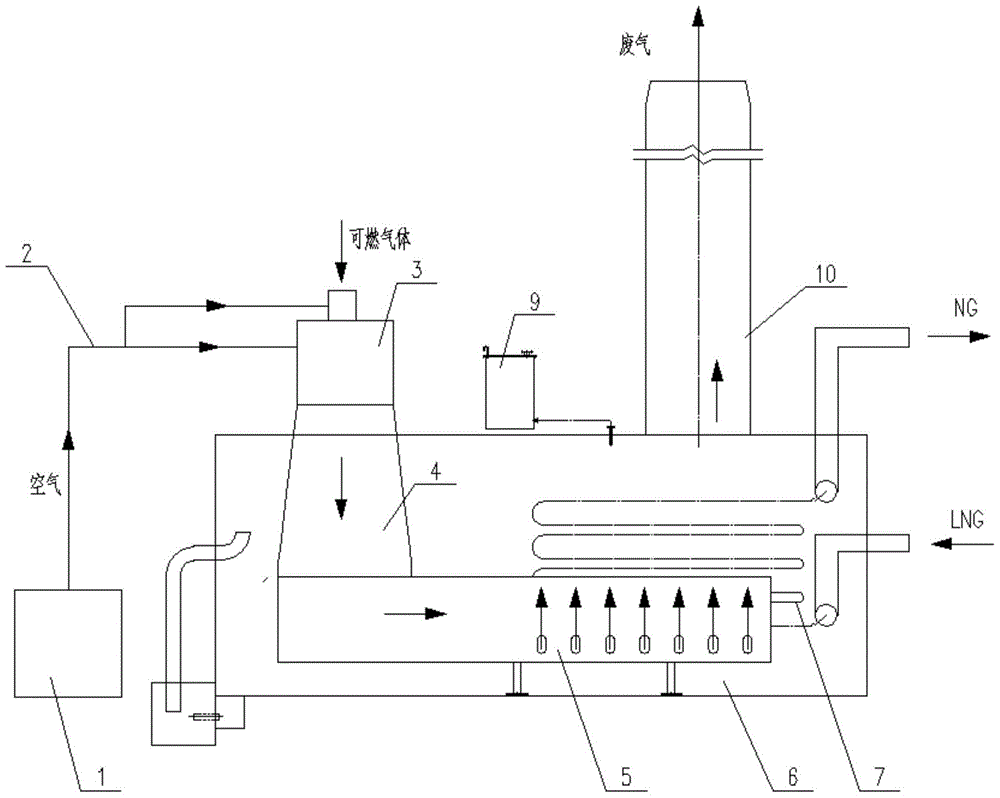
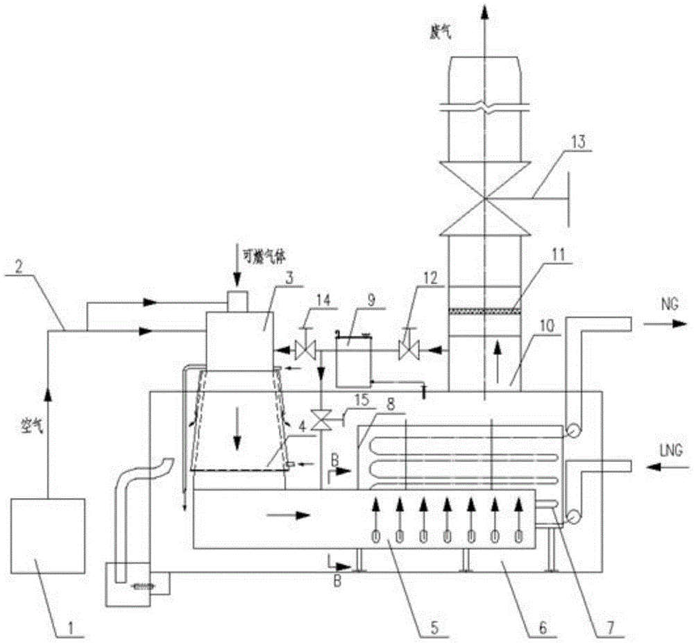
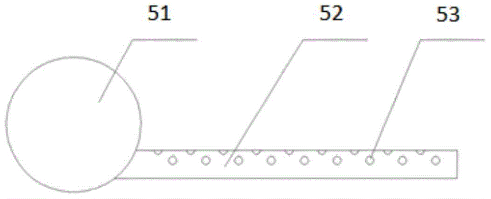
[0029] Such as figure 2 , 3As shown in and 4, an energy-saving submerged combustion gasifier includes a blower 1, an air duct 2, a burner 3, a combustion chamber 4, a flue gas distributor 5, a water tank 6, a heat exchange tube bundle 7, and a weir flow box 8, lye tank 9, chimney 10, gas-liquid separator 11, chimney regulating valve 13; described blower 1 links to each other with the air inlet of burner 3 through air duct 2, and the outlet of described burner 3 is located at The combustion chamber 4 on one side of the water tank 6 is connected, and the air in the burner 3 is fully mixed with the combustible gas entering from the gas inlet of the burner 3, and enters the combustion chamber 4 after ignition to generate high-temperature flue gas; The periphery of the combustion chamber 4 is provided with a water jacket 43, the...


PUM


Abstract

The invention discloses an energy-saving submerged combustion type gasifier, comprising a blower, an air duct, a burner, a combustion chamber, a flue gas distributor, a water tank, a heat exchange tube bundle, a weir flow box, a lye tank, a chimney and a gas Liquid separator and chimney regulating valve; the flue gas distributor includes a collecting pipe and a bubbling pipe, one end of the bubbling pipe is connected with the collecting pipe, the bubbling pipe is located under the heat exchange tube bundle, and at least one row of jets is arranged on the top of each bubbling pipe Holes; the weir box is supported by a bracket fixed at the bottom of the water tank, and the heat exchange tube bundle is suspended and supported by the hanging support structure on the top of the weir box, and is immersed in the water bath in the water tank; a gas-liquid separator is installed inside the chimney; the chimney The lower part is provided with a bypass, the bypass is connected with the burner through the first branch, and the bypass is connected with the flue gas distributor through the second branch. The invention has good heat exchange effect and high thermal efficiency, makes the gasification device more compact in structure, small in floor space, saves energy and cost, and is especially suitable for the LNG receiving station with the amount of gasification in processing.

Description

technical field [0001] The invention belongs to the technical field of liquefied natural gas gasification, and relates to an energy-saving submerged combustion gasifier, in particular to a submerged combustion gasifier for gasifying low-temperature liquids. The submerged combustion gasifier is often used in It is used as a liquefied natural gas gasification device in a large liquefied natural gas receiving station. Background technique [0002] With the continuous development of my country's industrialization level and energy conservation and emission reduction work, the demand and use of energy, especially clean energy, have become more and more prominent. As an energy source, natural gas has the dual advantages of high efficiency and cleanliness, and has been widely used at home and abroad in recent years. my country's National Energy Administration proposes to increase the proportion of natural gas in primary energy to 12% by 2020. It is estimated that by 2020, my count...

Claims


Application Information

Patent Timeline
Patent Type & Authority Patents(China)
IPC IPC(8): F17C7/04F24H7/02
Inventor 郭宏新刘丰田朝阳高原原刘世平李奇
Owner 江苏中圣压力容器装备制造有限公司
Why Eureka
Try Eureka