
Double-station type high-frequency vacuum dryer and implementation method thereof

A vacuum dryer and double-station technology, applied in the direction of local agitation dryers, static material dryers, dryers, etc., can solve the problems of poor use effect, low production efficiency, poor drying effect, etc., and achieve circulation system Perfect, wide application range, good effect

Active Publication Date: 2015-12-16
东阳市尚德电器机械有限公司
View PDF6 Cites 3 Cited by
  • Summary
  • Abstract
  • Description
  • Claims
  • Application Information

AI Technical Summary

Problems solved by technology

[0003] (1), low production efficiency;
[0004] (2), only suitable for mahogany and other wood, white wood is not applicable;
[0005] (3) Uneven heating and poor drying effect;
[0006] (4) The vacuum pump circulation system is easily damaged;
[0007] (5), the condensation effect is poor, and the water circulation system is not perfect;
[0008] (6) The use effect is poor and cannot meet customer needs

Method used


Image

  • Double-station type high-frequency vacuum dryer and implementation method thereof
  • Double-station type high-frequency vacuum dryer and implementation method thereof

Examples


Embodiment 1

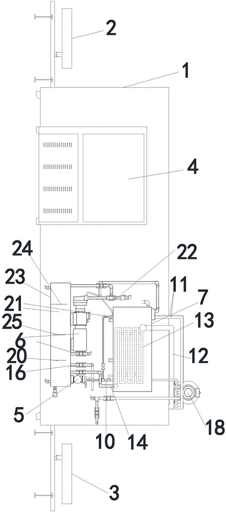
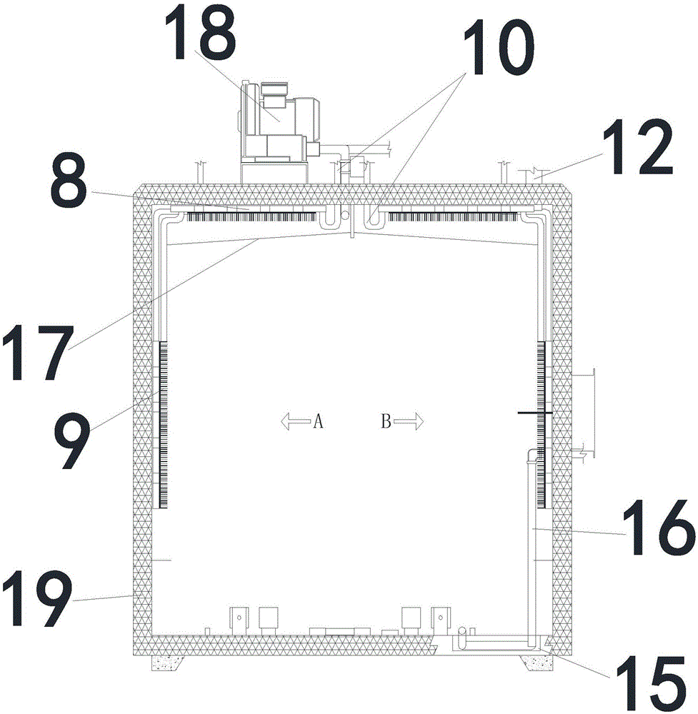
[0049] Such as Figure 1~2As shown, a double-station type high-frequency vacuum dryer includes a box body. The box body adopts a front door and a rear door. There is a high-frequency machine on the side, and a water collection tank system is installed on the side of the high-frequency machine. A water circulation pump is installed on the water collection tank system. The water circulation pump is connected to the cooling end of the vacuum pump through a pipeline, and the vacuum pump is connected to the top of the upper water tank through a pipeline; the water circulation pump is connected to the top of the water tank through a pipeline. It is connected to the first condensation sheet on the top of the box and the second condensation sheet on the side. The pipes of the first condensation sheet and the second condensation sheet in the box are connected in parallel. There is a condensation outlet pipe on the top of the box, and the condensation outlet pipe is connected to The top...

Embodiment 2

[0070] The difference between this embodiment and embodiment 1 is: the water collection tank in this embodiment is connected to the cooling pump; the second horizontal pipe is in the shape of an "S", and the purpose of the design is to improve the use effect. It has been proved by experiments that the qualified rate is increased by 12%. Above; the present embodiment also includes a controller, the controller is respectively connected with the high-frequency machine, the water circulation pump, the water collection tank system and the gas circulation system, and the controller is also connected with the Internet of Things, and the step (4) vacuum pump starts to work, so that the box The negative pressure in the body is 0.03MPa; after the test in step (6) is normal, let go of the vacuum, and adjust the high-frequency machine to 46 degrees Celsius; in step (7), the temperature rises slowly, not exceeding 3 degrees Celsius per hour, until it rises to 46 degrees Celsius ; In step (1...


PUM


Abstract

The invention discloses a double-station type high-frequency vacuum dryer. The double-station type high-frequency vacuum dryer comprises a box body which is provided with a front opening door and a back opening door, wherein a front material trolley is arranged at the front opening door, and a rear material door is arranged at the back opening door; a high-frequency machine is arranged on the side edge of the outer part of the box body; a water collecting box system is arranged on the side edge of the high-frequency machine; a water circulating pump, which is connected with a vacuum pump through a pipeline, is arranged on the water collecting box system; the vacuum pump is connected to the top part of a water filling box through the pipeline. The double-station type high-frequency vacuum dryer has the characteristics of being simple in structure, low in cost, high in production efficiency, wide in scope of application, and complete in circulating systems, saving energy and reducing emission, and being outstanding in condensing effect and good in use effect.

Description

technical field [0001] The invention relates to wood drying technology, in particular to a double-station high-frequency vacuum dryer and a realization method thereof. Background technique [0002] The existing high-frequency vacuum high-temperature and high-humidity integrated drying oven uses side stainless steel condensation sheets, and water drips after condensation, so awnings and welding parts are required. Such as Chinese patent, patent number: 201120281493.2, a rectangular high-frequency vacuum combined drying box, including a high-frequency heating device, a vacuum box, a water storage tank, a vacuum pump system, a timber car and a track, the shape of the vacuum box and each front section are Rectangular, the vacuum box is equipped with a built-in condenser, and the outside of the vacuum box is provided with an insulation layer; however, the following technical problems still exist: [0003] (1) Low production efficiency; [0004] (2), only suitable for mahogany a...

Claims


Application Information

Patent Timeline
Patent Type & Authority Applications(China)
IPC IPC(8): F26B5/06F26B9/06F26B25/00
Inventor 包淳德
Owner 东阳市尚德电器机械有限公司
Learn More