Coherent wind measurement laser radar system with adjustable range resolution

A technology of distance resolution and laser radar, which is applied in the direction of radio wave measurement system, measurement device, climate sustainability, etc., can solve the problem of the increase of full width at half maximum of spectral signal, the annihilation of signal light spectrum, and the inability to effectively improve coherent wind measurement laser radar Issues such as distance resolution to achieve the effect of improving applicability and reliability

Active Publication Date: 2015-12-16
UNIV OF SCI & TECH OF CHINA
View PDF1 Cites 27 Cited by
  • Summary
  • Abstract
  • Description
  • Claims
  • Application Information

AI Technical Summary

Problems solved by technology

Therefore, according to formula (3) and formula (5), it can be seen that improving the range resolution of coherent wind lidar needs to reduce the full width at half maximum of the pulse, which leads to the increase of the full width at half maximum of the spectral signal
from figure 2 Shown is the laser pulse width ΔT = 40ns, υ M =80MHz, the signal light spectrum annihilates the time domain diagram and frequency domain diagram under the condition of the local oscillator light spectrum, the meaning of the spectrum curve in the figure and the meaning of the marks A, B, and C are the same as the above figure 1 Similar; it can be seen that when ΔT is reduced by 10 times from 400ns to 40ns, the spectral width of local oscillator light and signal light is also broadened by 10 times, if still take υ M =80MHz, it will cause the signal light spectrum to be annihilated in the local oscillator light spectrum, such as figure 2 As shown in (II), Δυ cannot be accurately measured
Therefore, only by reducing the full width at half maximum of the laser pulse ΔT, instead of υ M Optimization cannot effectively improve the range resolution of coherent wind lidar

Method used


Image

  • Coherent wind measurement laser radar system with adjustable range resolution
  • Coherent wind measurement laser radar system with adjustable range resolution
  • Coherent wind measurement laser radar system with adjustable range resolution

Examples


Embodiment

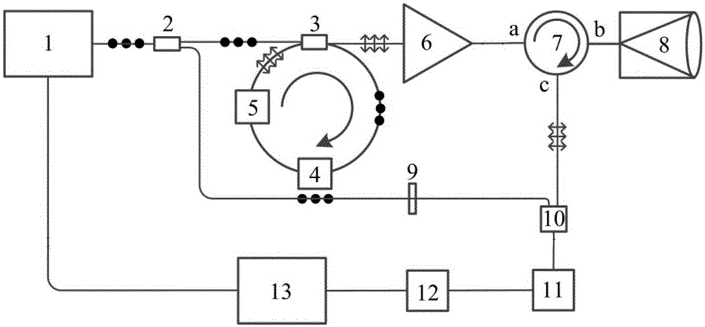
[0039] image 3 It is a schematic diagram of a coherent wind lidar system with adjustable range resolution provided by an embodiment of the present invention. Such as image 3 As shown, it mainly includes: continuous wave laser 1, 1-to-2 fiber beam splitter 2, polarization ring beam splitter 3, acousto-optic modulator (AOM) 4, electro-optic modulator (EOM) 5, amplifier 6, three-port ring Device 7, transmitting and receiving telescope 8, λ / 2 wave plate 9, fiber coupler 10, balance detector 11, acquisition card 12, computer 13; Wherein:

[0040] The continuous wave laser 1 is connected to the computer 13 and the 1-to-2 optical fiber beam splitter 2 respectively;

[0041] One end of 1-to-2 optical fiber beam splitter 2 is connected to polarization ring beam splitter 3, one end of polarization ring beam splitter 3 is connected to AOM4, AOM4 is connected to EOM5, and EOM5 is connected to polarization ring beam splitter 3 to form a loop The other end of the polarizing circular be...


PUM


Abstract

The invention discloses a coherent wind measurement laser radar system with adjustable range resolution. In one aspect, the system employs a polarization circular beam splitter 3, locks vertical polarized light in a circular device, and repeatedly passes through AOM to allow emitted laser to generate n upsilon M frequency shift, thereby adjusting laser frequency shift; in another aspect, the system employs EOM 5 to cooperate with the polarization circular beam splitter 3, converts the polarization state of the laser in the circular device reaching preset offset into parallel vibration from vertical polarization, and converts continuous wave laser into pulse width adjustable pulsed light, thereby realizing the adjustment of the range resolution of a coherent wind measurement laser radar. The scheme not only improves the applicability of the coherent wind measurement laser radar on different resolution requirement occasions and under different weather, but also improves the data measurement reliability of the coherent wind measurement laser radar.

Description

technical field [0001] The invention relates to the technical field of laser radar, in particular to a coherent wind measuring laser radar system with adjustable distance resolution. Background technique [0002] Accurate atmospheric wind field measurement is of great significance for detecting atmospheric pollution, obtaining military environmental intelligence, improving aerospace safety, improving the accuracy of weather forecasts, and improving climate models. Wind lidar is an effective means of wind field measurement at present, and it is divided into direct detection wind lidar and coherent detection wind lidar. The direct detection and wind measurement lidar converts the change of the echo signal frequency of the emitted laser into the relative change of energy to realize the measurement of the Doppler frequency shift of the atmospheric wind field. The coherent beat frequency of the signal and the local oscillator laser realizes the measurement of the Doppler frequen...

Claims


Application Information

Patent Timeline
Patent Type & Authority Applications(China)
IPC IPC(8): G01S17/95
CPCG01S17/95Y02A90/10
Inventor 王冲夏海云上官明佳窦贤康裘家伟
Owner UNIV OF SCI & TECH OF CHINA
Why Eureka
Try Eureka