Triangulation ray tracing path searching method
A ray tracing and path searching technology, which is applied in image data processing, 3D image processing, instruments, etc., can solve the problems of low program execution efficiency, long operation time, and excessive computational load, and achieves fewer triangles, computational complexity, etc. The effect of improving efficiency and reducing operation time
- Summary
- Abstract
- Description
- Claims
- Application Information
AI Technical Summary
Problems solved by technology
Method used
Image
Examples
Embodiment 1
[0020] The present invention proposes a triangulated ray tracing path search method, see figure 1 , the method includes the following steps:
[0021] 101: Define the normal vector of each triangle, facing outward relative to the right prism (it is considered that space objects are composed of several right prisms, each right prism is a closed space, and the normal vector of each surface is relative to the right prism where the surface is located Facing outward), make dot product between ray direction vector and triangle normal vector, and discard triangles whose dot product is greater than zero;
[0022] That is, first simplify the scene model to be composed of right prisms, divide the whole model into object objects, and then further divide the surface elements, each surface element is a polygon. Each polygonal surfel is then triangulated.
[0023] 102: Obtain the distance between each ray and the center of each triangle, and discard the triangle if the distance is greater ...
Embodiment 2
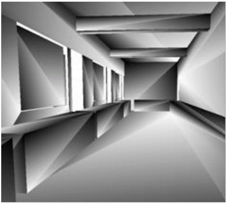
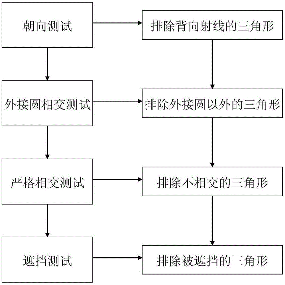
[0028] Below in conjunction with specific formula, accompanying drawing the scheme in embodiment 1 is described in detail, figure 1 It is an openGL window program written in C# language in the VisualStudio2010 environment to extract the scene information from a 3D indoor scene file (.dxf format) and triangulate the visualized running results. figure 2 For a detailed description of this method, see below:
[0029] 201: Triangle orientation test;
[0030] Define the normal vector of each triangle, facing outwards relative to the right prism (it is considered that space objects are composed of several right prisms, each right prism is a closed space, and the normal vector of each face is outward relative to the right prism where the face is located towards). For each ray, make a dot product between the ray direction vector and the triangle normal vector, and discard the triangle whose dot product is greater than zero (indicating that the triangle normal vector is in the same d...
Embodiment 3
[0044] Below in conjunction with concrete example, accompanying drawing, the scheme in embodiment 1 and 2 is carried out feasibility verification, see below for details:
[0045] The transmitting end adopts a vertically polarized antenna, the transmitting power is 10w, the frequency is 2.5GHz, and the antenna height is 2.2m. Apply this method to figure 1 In the indoor scene shown, the scale of the scene model is: 15×3×2.5(m 3 ). The radius of the receiving sphere is set to 0.045m, and the height of the receiving antenna is 1.5m. The simulation results of the scene model after the above steps are shown in Figure 4 . Figure 4 is true figure 1 After the path search algorithm is used in the scene, the running results of the path display are included. This method does not include the calculation process of the field strength. In actual situations, the rays are relatively dense. In order to display clearly, the interval between the rays used in this simulation is relatively lar...
PUM
 Abstract
Description
Claims
Application Information
 - R&D
- Intellectual Property
- Life Sciences
- Materials
- Tech Scout
- Unparalleled Data Quality
- Higher Quality Content
- 60% Fewer Hallucinations
Browse by: Latest US Patents, China's latest patents, Technical Efficacy Thesaurus, Application Domain, Technology Topic, Popular Technical Reports.
© 2025 PatSnap. All rights reserved.Legal|Privacy policy|Modern Slavery Act Transparency Statement|Sitemap|About US| Contact US: help@patsnap.com


