Eureka AIR delivers breakthrough ideas for toughest innovation challenges, trusted by R&D personnel around the world.

Shift register unit, operation method for shift register unit and shift register

A shift register and control signal technology, applied in static memory, digital memory information, instruments, etc., can solve problems such as inability to meet product requirements, and achieve the effect of reducing reset time

Active Publication Date: 2015-12-16
BOE TECH GRP CO LTD
View PDF6 Cites 31 Cited by
  • Summary
  • Abstract
  • Description
  • Claims
  • Application Information

AI Technical Summary

Problems solved by technology

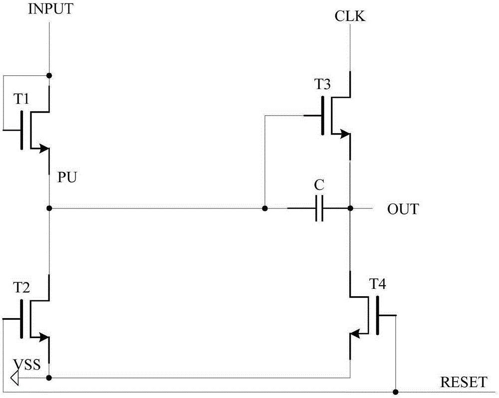
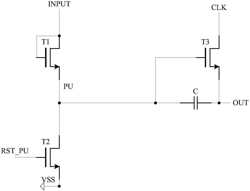
Although in image 3 The output reset transistor T4 is omitted, however, with the further improvement of display resolution and the further improvement of narrow border requirements, image 3 The shift register cell shown is still not sufficient for the product

Method used


Image

  • Shift register unit, operation method for shift register unit and shift register
  • Shift register unit, operation method for shift register unit and shift register
  • Shift register unit, operation method for shift register unit and shift register

Examples


Embodiment Construction

[0038] In order to make the objects, technical solutions, and advantages of the embodiments of the present invention more apparent, exemplary embodiments of the present invention will be described in detail below with reference to the accompanying drawings. Apparently, the described exemplary embodiments are only some embodiments of the present invention, rather than all embodiments of the present invention, and all other embodiments obtained by those skilled in the art without paying creative efforts should fall into the present invention. within the scope of protection of the invention.

[0039] Here, it is to be noted that, in the drawings, the same reference numerals are assigned to components having substantially the same or similar structures and functions, and repeated descriptions about them will be omitted.

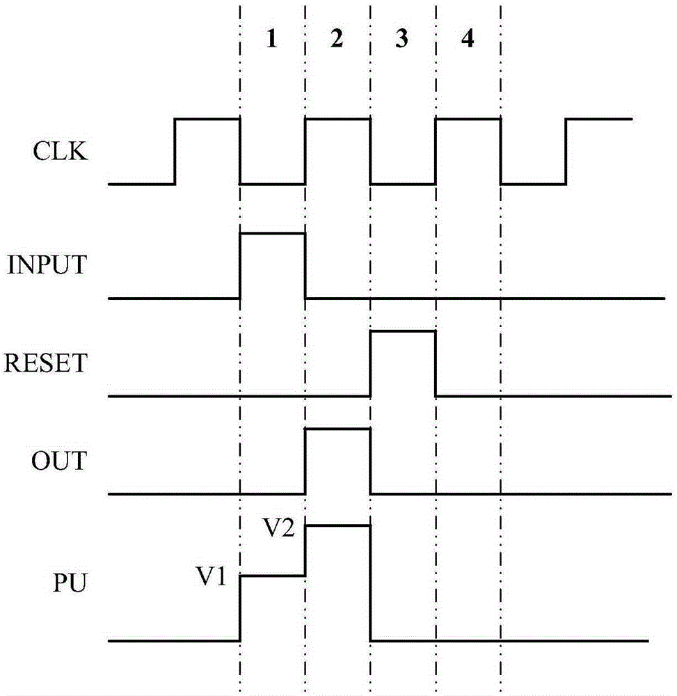
[0040] Such as figure 1 As shown, a schematic structural diagram of a shift register unit in the prior art is shown. The shift register unit includes an input ...


PUM


Abstract

Disclosed are a shift register unit, an operation method for the shift register unit and a shift register comprising the shift register unit. The shift register unit comprises an input module configured to transmit a received input signal to a pull-up node, an output module configured to output a first control signal of a first control signal end to an output end when a pull-up signal at the pull-up node is in effective pull-up level, and a coupling module of which a first end is connected with a second control signal end and a second end is connected with the pull-up node, and configured to control the pull-up signal at the pull-up node according to a second control signal of the second control signal end in a voltage-coupling mode. By further increasing the voltage at the pull-up node during resetting of the output end, the resetting speed of the output end can be increased.

Description

technical field [0001] The present invention relates to the display field, and more particularly relates to a shift register unit, an operation method thereof, and a shift register including the shift register unit. Background technique [0002] Currently, in the circuit structure of the shift register unit, the output end of the shift register unit and the pull-up node are simultaneously reset by using a special output reset transistor and a node reset transistor. Such as figure 1 As shown, the gates of the output reset transistor T4 and the node reset transistor T2 of the shift register unit are connected to the reset input terminal, and the output terminal and the pull-up node are respectively reset under the control of the reset signal output from the reset input terminal. In order to reduce the reset time of the shift register unit, it is necessary to increase the area of ​​the output reset transistor T4 so that the turn-on voltage of the output reset transistor T4 is ...

Claims


Application Information

Patent Timeline
Patent Type & Authority Applications(China)
IPC IPC(8): G11C19/28
CPCG09G3/20G09G2310/0267G09G2310/061G09G2320/0252G09G2310/0286G11C19/287G09G3/2096G11C19/186
Inventor 商广良
Owner BOE TECH GRP CO LTD
Why Eureka
Eureka Blog
Learn More