
Low-resistance transmission circuit for CVP probe active integration method

A transmission circuit and integral method technology, applied in the field of signal transmission, can solve the problems of inability to transmit coaxial cables, attenuation of high-frequency components of signals, and loss of differential signals.

Inactive Publication Date: 2015-12-16
INST OF FLUID PHYSICS CHINA ACAD OF ENG PHYSICS
View PDF4 Cites 0 Cited by
  • Summary
  • Abstract
  • Description
  • Claims
  • Application Information

AI Technical Summary

Problems solved by technology

The coaxial cable of tens to one hundred meters or more transmits the differential signal to the terminal, and the loss of the front and rear edges of the differential signal is serious. This is due to the attenuation of the high frequency component of the signal due to the limitation of the bandwidth of the coaxial cable, and the use has certain limitations.
However, the voltage waveform after integration in the high-impedance state cannot be transmitted by coaxial cables, and is limited by the low-impedance characteristics.

Method used


Image

  • Low-resistance transmission circuit for CVP probe active integration method

Examples


Embodiment Construction

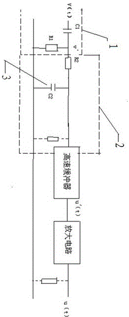
[0017] The main object of the present invention is the voltage waveform test of the high-voltage fast pulse acceleration chamber, usually a single square wave pulse with a waveform bandwidth of tens of megahertz and an amplitude of several hundred kilovolts. Therefore, the low-resistance transmission technology of the CVP probe active integration method in the present invention utilizes the principle of impedance transformation technology to advance the terminal integration resistance in its traditional test, which is infinitely close to the integration capacitance and forms an integration unit, and the integration capacitance is made into a coaxial type And without any leads; as the input circuit of the impedance transformation unit, it is directly connected to the differential unit of the CVP probe, so that the differential signal is directly sent to the integration unit without any transmission, ensuring that the differential signal is integrated without loss, and the voltage...


PUM


Abstract

The invention discloses a low-resistance transmission circuit based on a CVP probe active integration method. The low-resistance transmission circuit consists of a CVP probe unit, an integration unit and an impedance conversion unit, wherein high-voltage pulse square waves are input into an input end of the CVP probe unit; high resistance is set between integration signal output circuits of an RC integration circuit; low resistance is set between output circuits of the impedance conversion unit; and the output circuits of the impedance conversion unit are directly connected to a signal transmission line. Through adoption of the low-resistance transmission circuit, a low-resistance transmission technology based on the CVP probe active integration method is realized under the situation that technical problems in a general integration method are solved completely. An active integrator is directly connected with a CVP probe output end, so that the influence of a long cable on a differential signal high-frequency component is eliminated, and the problem that general test measures such as integration signal transmission (long cables or optical fibers), impedance matching, signal shutting or overlapping cannot be taken on the aspect of testing technology is well solved.

Description

technical field [0001] The invention relates to the field of signal transmission, in particular to a low-resistance transmission circuit of a CVP probe active integration method. Background technique [0002] Linear induction accelerator (hereinafter referred to as LIA) high-voltage fast-pulse acceleration chamber voltage waveform test, usually a single square wave pulse with a waveform bandwidth of tens of megahertz and an amplitude of several hundred kilovolts. Usually, the CVP probe and the cable load are used to differentiate the original signal, and then integrated and restored through the remote integrating box (integrating resistance is the input resistance of the oscilloscope) to obtain the voltage waveform of the accelerating chamber. However, the signal transmission cable of this method is usually long, making the differential signal The loss of high-frequency components is serious, resulting in distortion of the restored waveform. [0003] The measurement of the ...

Claims


Application Information

Patent Timeline
Patent Type & Authority Applications(China)
IPC IPC(8): H03K3/64H03F1/32G01R19/00
Inventor 马冰季万涛赖青贵
Owner INST OF FLUID PHYSICS CHINA ACAD OF ENG PHYSICS
Learn More