Data flow positioning method and device

A technology of data flow and positioning method, applied in the fields of electrical components, wireless communication, network planning, etc., can solve the problem of inability to provide effective reference for WLAN and LTE site construction and site selection, unfavorable positioning of high-traffic areas and high-value areas, and data has not yet been proposed. Traffic positioning scheme and other issues to achieve the effect of improving the accuracy of site location selection

Active Publication Date: 2015-12-16
CHINA MOBILE COMM GRP CO LTD
View PDF7 Cites 5 Cited by
  • Summary
  • Abstract
  • Description
  • Claims
  • Application Information

AI Technical Summary

Problems solved by technology

Unlike circuit switching (CircuitSwitch, CS) services, 2G network packet switching (PacketSwitch, PS) service connection status does not report MR signaling, and the MR positioning method commonly used for accurate positioning of CS services is no longer applicable. At present, it has not been proposed for The data traffic positioning scheme for PS services is not conducive to the positioning of high-traffic areas and high-value areas, making it impossible to provide effective reference for the construction site selection of WLAN and LTE sites

Method used


Image

  • Data flow positioning method and device
  • Data flow positioning method and device
  • Data flow positioning method and device

Examples


Embodiment 1

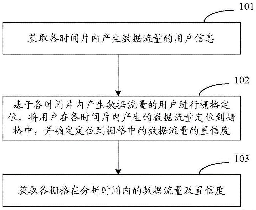
[0059] figure 1 It is a schematic flowchart of a data traffic location method according to an embodiment of the present invention, as shown in figure 1 As shown, the method includes:

[0060] Step 101: Acquiring user information generating data traffic in each time slice;

[0061] Here, the analysis time needs to be divided into more than one time slice, and the divided time slices should be small enough to ensure the time granularity that the user does not generate a large displacement.

[0062] Step 102: Perform grid positioning based on users who generate data traffic in each time slice, locate the data traffic generated by users in each time slice into the grid, and determine the confidence of the data traffic positioned in the grid;

[0063] Here, grid positioning may be performed on all or part of users that generate data traffic in each time slice. For example, only users whose ratio of the data traffic generated in a time slice to the total data traffic in the time ...

Embodiment 2

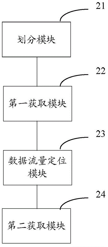
[0089] figure 2 It is a schematic structural diagram of a data traffic locating device in Embodiment 2 of the present invention, which corresponds to the data traffic locating method described in Embodiment 1, as shown in figure 2 As shown, the device includes: a division module 21, a first acquisition module 22, a data traffic location module 23, and a second acquisition module 24; wherein,

[0090] A division module 21, configured to divide the analysis time into more than one time slice;

[0091] The first obtaining module 22 is used to obtain user information that generates data traffic in each time slice;

[0092] The data traffic positioning module 23 is configured to perform grid positioning based on users who generate data traffic in each time slice, locate the data traffic generated by users in each time slice into the grid, and determine the data traffic positioned in the grid confidence level;

[0093] The second acquisition module 24 is configured to acquire t...

Embodiment 3

[0107] Figure 4 It is a schematic flow chart of the data traffic location method described in Embodiment 3 of the present invention, as shown in Figure 4 As shown, the process includes:

[0108] Step 401: Obtain the total data traffic flow in a specified area and analysis time, and divide the analysis time into a plurality of sufficiently small time slices.

[0109] Here, the total data flow of the selected range and collection time is collected.

[0110] Step 402: Extract user information and cell information that generate traffic within the time slice.

[0111] Step 403: Select the kth user that generates traffic, and judge whether the user has a voice service within the time slice, if yes, execute step 404; otherwise, execute step 405.

[0112] Step 404: Obtain the MR of the user that occurred in the same cell within the time slice, perform grid positioning, and go to step 406.

[0113] Step 405: Determine if it is possible to find an alternative MR that occurred in t...


PUM


Abstract

The embodiment of the invention discloses a data flow positioning method. The method includes the steps: dividing analysis time into more than one time slice, and obtaining the information of users producing data flows within all time slices; positioning the data flows produced by the users within the time slices in grids, and determining the confidence of the data flows positioned in the grids; and obtaining the data flows and the confidence of the grids within the analysis time. The embodiment of the invention also discloses a data flow positioning device. The device includes: a dividing module, which divides analysis time into more than one time slice; a first obtaining module, which obtains the information of users producing data flows within all time slices; a data flow positioning module, which positions the data flows produced by the users within the time slices in grids and determines the confidence of the data flows positioned in the grids; and a second obtaining module, which obtains the data flows and the confidence of the grids within the analysis time.

Description

technical field [0001] The invention relates to wireless communication technology, in particular to a data flow positioning method and device. Background technique [0002] In multi-network collaboration such as Global System for Mobile Communication (GSM), 3G, Wireless Local Area Networks (WLAN), and Long Term Evolution (LTE), the offloading of 2G high-traffic and high-load cells is one of the goals. Through reasonable planning and construction of WLAN and LTE sites, it is an important means to realize effective offloading of 2G cells, and it is also a difficulty in implementation. Because the coverage of WLAN and LTE sites is smaller than 2G cells, it is necessary to analyze the data service traffic in the area during site planning, and perform precise positioning on the grid to geographically present the service traffic in a finer-than-cell area, and to assist O&M personnel in locating the network High-traffic areas and high-value areas guide the site selection of WLAN a...

Claims


Application Information

Patent Timeline
Patent Type & Authority Applications(China)
IPC IPC(8): H04W16/18
Inventor 梁燕萍
Owner CHINA MOBILE COMM GRP CO LTD
Why Eureka
Try Eureka