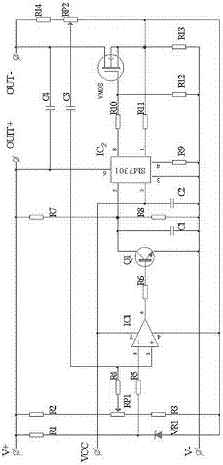
pwm ripple processing and constant current control circuit
A technology of constant current control circuit and ripple control, applied in electric lamp circuit layout, electric light source, lighting device, etc., can solve the problem of continuous service life being very different, and achieve the effect of solving the driving problem and prolonging the service life.
- Summary
- Abstract
- Description
- Claims
- Application Information
AI Technical Summary
Problems solved by technology
Method used
Image
Examples
Embodiment Construction
[0009] It is composed of constant current control circuit and ripple control circuit;
[0010] The so-called constant current control circuit is that the 6th pin of the PWM control chip IC2 is connected to the positive terminal V+ of the DC voltage, the 3rd pin is connected to the negative terminal V- of the DC voltage, and the 5th pin is the voltage regulation control terminal. The pull-up resistor R7 is connected to the positive terminal V+ of the DC voltage, and then connected to the negative terminal V- of the DC voltage through the pull-down resistor R8. The collector and emitter of the transistor Q1 are connected to both ends of the resistor R8, and the two ends of the resistor R8 are also Connected with capacitor C2, the 4th pin of the PWM control chip IC2 is connected to the negative terminal of the DC voltage, and the 8th pin is connected to the gate terminal of the VMOS tube through the resistor R10 to complete the input of the PWM signal, and the gate terminal of the...
PUM
 Abstract
Description
Claims
Application Information
 - R&D
- Intellectual Property
- Life Sciences
- Materials
- Tech Scout
- Unparalleled Data Quality
- Higher Quality Content
- 60% Fewer Hallucinations
Browse by: Latest US Patents, China's latest patents, Technical Efficacy Thesaurus, Application Domain, Technology Topic, Popular Technical Reports.
© 2025 PatSnap. All rights reserved.Legal|Privacy policy|Modern Slavery Act Transparency Statement|Sitemap|About US| Contact US: help@patsnap.com

