[0071] The solar heating system according to the present invention will be described in detail below with reference to the accompanying drawings.
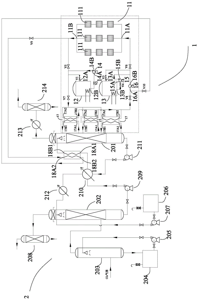
[0072] refer to figure 1 , according to the solar heating system 1 of the present invention, it communicates with the regeneration tower 201 of the gas chemical absorption and regeneration system 2, and is used to heat the gas-absorbing liquid in the regeneration tower 201. The solar heating system 1 includes a solar collector 11 , a high temperature heat transfer fluid storage tank 12 , a low temperature heat transfer fluid storage tank 13 , a high temperature heat transfer fluid pump 14 , a low temperature heat transfer fluid pump 15 , a heat transfer fluid circulation pump 16 and a multistage boiler 17 .
[0073] The solar heat collector 11 collects solar energy and has: a heat transfer fluid inlet 11A of the solar heat collector; and a heat transfer fluid outlet 11B of the solar heat collector.
[0074] The high-temperature heat-transfer fluid storage tank 12 has: a high-temperature heat-transfer fluid storage tank inlet 12A, which is controlled to communicate with the solar heat collector heat-transfer fluid inlet 11A; and a high-temperature heat-transfer fluid storage tank outlet 12B.
[0075] The low temperature heat transfer fluid storage tank 13 stores the low temperature heat transfer fluid, and has: a low temperature heat transfer fluid storage tank inlet 13A; and a low temperature heat transfer fluid storage tank outlet 13B.
[0076] The high-temperature heat-transfer fluid pump 14 has: a high-temperature heat-transfer fluid pump inlet 14A, which is controlled to communicate with the high-temperature heat-transfer fluid storage tank outlet 12B; and a high-temperature heat-transfer fluid pump outlet 14B.
[0077] The low temperature heat transfer fluid pump 15 has: a low temperature heat transfer fluid pump inlet 15A; a controlled connection to the low temperature heat transfer fluid storage tank outlet 13B; and a low temperature heat transfer fluid pump outlet 15B, a controlled connection to the solar heat collector heat transfer fluid outlet 11B.
[0078] The heat transfer fluid circulation pump 16 has: a heat transfer fluid circulation pump inlet 16A, a heat transfer fluid circulation pump outlet 16B, which is controlled to communicate with the heat transfer fluid inlet 11A of the solar collector and controlled to communicate with the low temperature heat transfer fluid storage tank inlet 13A.
[0079] The multi-stage boiler 17 is connected in parallel with the regeneration column 201 . Boilers 17 at all levels have: boiler rich liquid inlet 17A1, which is connected to regeneration tower 201; boiler heat transfer fluid inlet 17A2, which is controlled to be connected to solar heat collector heat transfer fluid outlet 11B and controlled to be connected to high temperature heat transfer fluid pump outlet 14B ; The rich liquid outlet 17B1 of the boiler is connected to the regeneration tower 201; and the heat transfer fluid outlet 17B2 of the boiler is connected to the heat transfer fluid circulation pump inlet 16A under control.
[0080] Wherein, when the solar heating system 1 adopts the daytime mode to work:
[0081] When the solar collector 11 is working, the low temperature heat transfer fluid pump inlet 15A is connected to the low temperature heat transfer fluid storage tank outlet 13B, the low temperature heat transfer fluid pump outlet 15B is connected to the solar collector heat transfer fluid inlet 11A, and the high temperature heat transfer fluid storage tank inlet 12A is connected to the solar collector. The heat transfer fluid outlet 11B of the collector, the heat transfer fluid inlet 17A2 of the boiler 17 of each level is connected to the heat transfer fluid outlet 11B of the solar collector, and the heat transfer fluid outlet 17B2 of the boiler 17 of each level is connected to the heat transfer fluid circulation pump inlet 16A, the heat transfer fluid circulation pump outlet 16B is connected to the heat transfer fluid inlet 11A of the solar collector, the high temperature heat transfer fluid pump inlet 14A is not connected to the high temperature heat transfer fluid storage tank outlet 12B, and the boiler heat transfer fluid inlet 17A2 of the boiler 17 at each level is not connected At the outlet 14B of the high-temperature heat-transfer fluid pump, the outlet 16B of the heat-transfer fluid circulation pump is not connected to the inlet 13A of the low-temperature heat-transfer fluid storage tank;
[0082] The low temperature heat transfer fluid pump 15 drives the low temperature heat transfer fluid in the low temperature heat transfer fluid storage tank 13 to pass through the low temperature heat transfer fluid storage tank outlet 13B, the low temperature heat transfer fluid pump inlet 15A, the low temperature heat transfer fluid pump 15, the low temperature heat transfer fluid pump outlet 15B, and the solar collector The heat transfer fluid inlet 11A enters the solar heat collector 11. In the solar heat collector 11, it exchanges heat with the solar energy absorbed by the solar heat collector 11. The low temperature heat transfer fluid absorbs heat and becomes a high temperature heat transfer fluid. The high temperature heat transfer fluid passes through the solar collector. The heat transfer fluid outlet 11B of the heater is discharged, and a part of the discharged high-temperature heat transfer fluid flows into the high-temperature heat transfer fluid storage tank 12 through the high-temperature heat transfer fluid storage tank inlet 12A for storage, while the other part of the discharged high-temperature heat transfer fluid is boiled through the boilers 17 of various stages. The heat transfer fluid inlet 17A2 enters the boilers 17 at all levels, and the rich liquid in the regeneration tower 201 enters the boilers 17 at all levels from the regeneration tower 201 through the rich liquid inlet 17A1 of the boilers. In the boilers 17 at all levels, the high temperature The heat transfer fluid exchanges heat with the rich liquid. The rich liquid absorbs heat and rises to the desorption temperature and returns to the regeneration tower 201 through the rich liquid outlet 17B1 of the boiler for desorption. The heat transfer fluid enters the heat transfer fluid circulation pump 16 through the heat transfer fluid outlet 17B2 of the boiler and the heat transfer fluid circulation pump inlet 16A, and then is discharged from the heat transfer fluid circulation pump outlet 16B. 15 The low-temperature heat-transfer fluid discharged through the outlet 15B of the low-temperature heat-transfer fluid pump joins together and enters the solar heat collector 11, and the cycle repeats.
[0083] When the solar thermal collection system works in night mode:
[0084] The solar heat collector 11 stops working, the low temperature heat transfer fluid pump 15 stops working, the low temperature heat transfer fluid pump inlet 15A is not connected to the low temperature heat transfer fluid storage tank outlet 13B, and the low temperature heat transfer fluid pump outlet 15B is not connected to the solar heat collector heat transfer fluid inlet 11A , the high-temperature heat transfer fluid storage tank inlet 12A is not connected to the solar heat collector heat transfer fluid outlet 11B, the boiler heat transfer fluid inlet 17A2 of the boiler 17 at each level is not connected to the solar heat collector heat transfer fluid outlet 11B, and the boilers 17 at all levels are not connected to each other. Boiler heat transfer fluid outlet 17B2 is connected to heat transfer fluid circulation pump inlet 16A, heat transfer fluid circulation pump outlet 16B is connected to low temperature heat transfer fluid storage tank inlet 13A, heat transfer fluid circulation pump outlet 16B is not connected to solar collector heat transfer fluid inlet 11A, high temperature The heat transfer fluid pump inlet 14A is connected to the high temperature heat transfer fluid storage tank outlet 12B, and the boiler heat transfer fluid inlet 17A2 of the boilers 17 at each stage is connected to the high temperature heat transfer fluid pump outlet 14B;
[0085] The high temperature heat transfer fluid pump 14 drives the high temperature heat transfer fluid in the high temperature heat transfer fluid storage tank 12 from the high temperature heat transfer fluid storage tank 12 via the high temperature heat transfer fluid storage tank outlet 12B via the high temperature heat transfer fluid pump inlet 14A, the high temperature heat transfer fluid pump 14, the high temperature heat transfer fluid The pump outlet 14B and the boiler heat transfer fluid inlet 17A2 of the boilers 17 of each stage enter into the boilers 17 of each stage, and at the same time, the rich liquid in the regeneration tower 201 enters the boilers 17 of each stage from the rich liquid inlet 17A1 of the boiler. In the boiler 17, the high-temperature heat transfer fluid exchanges heat with the rich liquid. The rich liquid absorbs heat and heats up to the desorption temperature and returns to the regeneration tower 201 through the rich liquid outlet 17B1 of the boiler for desorption. The high-temperature heat transfer fluid releases heat and cools down to a low temperature. Circulating heat transfer fluid, the low-temperature circulating heat transfer fluid enters the heat transfer fluid circulation pump 16 through the boiler heat transfer fluid outlet 17B2 and the heat transfer fluid circulation pump inlet 16A, and then is discharged from the heat transfer fluid circulation pump outlet 16B, and the low-temperature circulation heat transfer fluid discharged through the heat transfer fluid circulation pump outlet 16B The fluid enters the low-temperature heat-transfer fluid storage tank 13 through the low-temperature heat-transfer fluid storage tank inlet 13A and is stored as a low-temperature heat-transfer fluid.
[0086] In the solar heating system 1 according to the present invention, the solar heat collector 11 collects solar energy and makes full use of the solar energy, instead of steam heating, thereby reducing energy consumption; at the same time, the regeneration of the multistage boiler 17 and the gas chemical absorption and regeneration system 2 is adopted The towers 201 are connected in parallel, and the high-efficiency heat collection capacity of solar energy is used to fully meet the desorption temperature requirement of the rich liquid.
[0087] In gas chemical absorption and regeneration system 2, the gas is CO 2 , the rich solution can absorb CO 2 Alcoholamine solution (as absorbent), of course not limited thereto, the gas chemical absorption and regeneration system 2 can be applied to any suitable gas and absorbent.
[0088] In the gas chemical absorption and regeneration system 2, the gas-absorbing rich liquid can absorb the gas by chemical absorption or physical absorption.
[0089] In one embodiment, refer to figure 1 The solar heat collector 11 includes a plurality of solar heat collectors 111 arranged in an array, the solar heat collectors 111 in each row can be connected in series, and the solar heat collectors 111 in all rows can be connected in parallel.
[0090] In one embodiment, the solar heat collector 111 uses a vacuum tube.
[0091] In an embodiment, the heat transfer fluid may be heat transfer oil, of course it is not limited thereto, and any suitable heat transfer fluid may be used.
[0092] In one embodiment, refer to figure 1 In addition to the lowest primary boiler 17 of the multi-stage boiler 17, the boiler rich liquid inlet 17A1 of the boiler 17 of other stages is connected to the regeneration tower 201 and the boiler rich liquid outlet 17B1 is connected to the regeneration tower 201. The location corresponds to a liquid redistributor (not shown) of regeneration column 201 .
[0093] In one embodiment, refer to figure 1, the controlled communication is achieved through the corresponding valves. Specifically, the valve V1 controls the communication between the heat transfer fluid outlet 11B of the solar collector and the high temperature heat transfer fluid storage tank inlet 12A; the valve V2 controls the communication between the high temperature heat transfer fluid storage tank outlet 12B and the high temperature heat transfer fluid pump inlet 14A; the valve V3 controls the communication between the heat transfer fluid circulation pump outlet 16B and the low temperature heat transfer fluid storage tank inlet 13A; the valve V4 controls the communication between the low temperature heat transfer fluid storage tank outlet 13B and the low temperature heat transfer fluid pump inlet 15A; the valve V5 controls the solar collector The communication between the heat transfer fluid outlet 11B and the high temperature heat transfer fluid storage tank inlet 12A; the valve V6 controls the communication between the heat transfer fluid circulation pump outlet 16B and the solar heat collector heat transfer fluid inlet 11A; the valve V7 controls the high temperature heat transfer fluid pump outlet 14B and The communication between the boiler heat transfer fluid inlet 17A2 of the boilers 17 at all levels; the valve V8 controls the communication between the boiler heat transfer fluid outlet 17B2 of the boilers 17 at all levels and the heat transfer fluid circulation pump inlet 16A; the valve V9 controls the solar heat collection The communication between the heat transfer fluid outlet 11B of the heat exchanger and the rich liquid outlet 18B1 of the heat exchanger; the valve V10 controls the communication between the heat transfer fluid inlet 18A2 of the preheating heat exchanger and the heat transfer fluid circulation pump inlet 16A.
[0094] In one embodiment, refer to figure 1 , the solar heating system 1 may also include a preheating heat exchanger 18 . The preheating heat exchanger 18 has: the rich liquid inlet 18A1 of the preheating heat exchanger is connected to the absorption tower 202 of the gas chemical absorption and regeneration system 2; the heat transfer fluid inlet 18A2 of the preheating heat exchanger is connected to the solar collector in a controlled manner The heat transfer fluid outlet 11B; the rich liquid outlet 18B1 of the heat exchanger is connected to the upper part of the regeneration tower 201; and the heat transfer fluid outlet 18B2 of the heat exchanger is controlled and connected to the heat transfer fluid circulation pump inlet 16A. Among them, the rich liquid from the absorption tower 202 enters the preheating heat exchanger 18 through the rich liquid inlet 18A1 of the preheating heat exchanger, and the high-temperature heat transfer fluid in the solar collector 11 passes through the heat transfer fluid outlet 11B of the solar collector and the preheating heat exchanger. The heat transfer fluid inlet 18A2 of the heater enters the preheating heat exchanger 18. In the preheating heat exchanger 18, the high temperature heat transfer fluid exchanges heat with the rich liquid. The heat rises, and the heated rich liquid exits the preheating heat exchanger 18 through the rich liquid outlet 18B1 of the preheating heat exchanger and enters the regeneration tower 201 through the upper part of the regeneration tower 201 for desorption, and the cooling heat transfer fluid passes through the preheating heat exchanger. The outlet 18B2 discharges and enters the heat transfer fluid circulation pump 16 through the heat transfer fluid circulation pump inlet 16A to participate in the daytime mode operation and the nighttime mode operation of the solar heating system 1 .
[0095] Finally, it is added here that, referring to figure 1 , the gas chemical absorption and regeneration system 2 may also include a washing tower 203, a sedimentation tank 204, a washing pump 205, an absorption liquid storage tank 206, a replenishment pump 207, a first separator 208, a rich liquid pump 209, and a lean-rich liquid heat exchanger 210, the lean liquid pump 211, the lean liquid cooler 212, the gas cooler 213 and the second separator 214, and the controlled communication among them is also realized through corresponding valves, and the functions and operations of these components are well known. Therefore, their explanations are omitted.