Spin Runoff Fountain

A spin-type, run-of-the-river technology, applied in the direction of injection devices, liquid injection devices, etc., can solve problems such as limited range, fountains cannot move up and down, and affect viewing effects, so as to reduce equipment volume and energy consumption and enrich viewing effects , the effect of enriching the viewing effect

Inactive Publication Date: 2017-12-01
NINGDE NORMAL UNIV
View PDF6 Cites 0 Cited by
  • Summary
  • Abstract
  • Description
  • Claims
  • Application Information

AI Technical Summary

Problems solved by technology

[0002] At present, although the existing fountain devices can produce rhythmic jumps with the music rhythm of the sound or directly with the rhythm of the external sound, and achieve a certain degree of appreciation through the combination of water and light and shadow, but the existing Fountain devices generally spray vertical or oblique fountains from multiple fixed spray holes, and the fountains have a single shape and poor flexibility
The revolving fountain represented by the publication number CN104384058A-a self-rotating multi-nozzle fountain, CN102527571A-a revolving fountain, CN201310151849-a revolving flying saucer fountain has been created on the diversity of fountains, improving the agility of fountains, However, none of the fountains can move up and down, and the range is limited, and the rotation of the fountain needs to be driven by another motor, which increases the volume of the equipment, relatively reduces the viewing field of view, and affects the viewing effect

Method used


Image

  • Spin Runoff Fountain
  • Spin Runoff Fountain
  • Spin Runoff Fountain

Examples


Embodiment 1

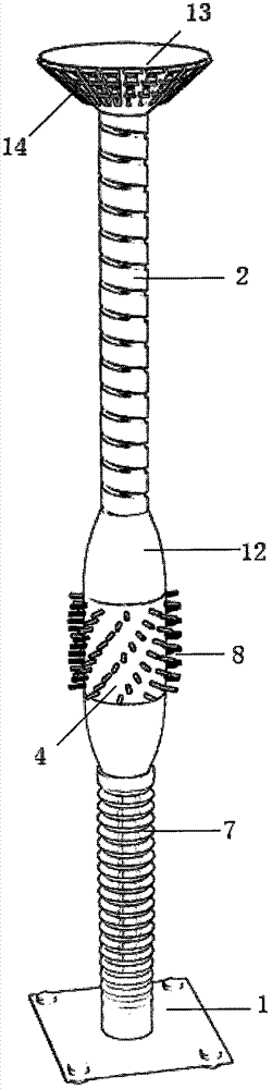
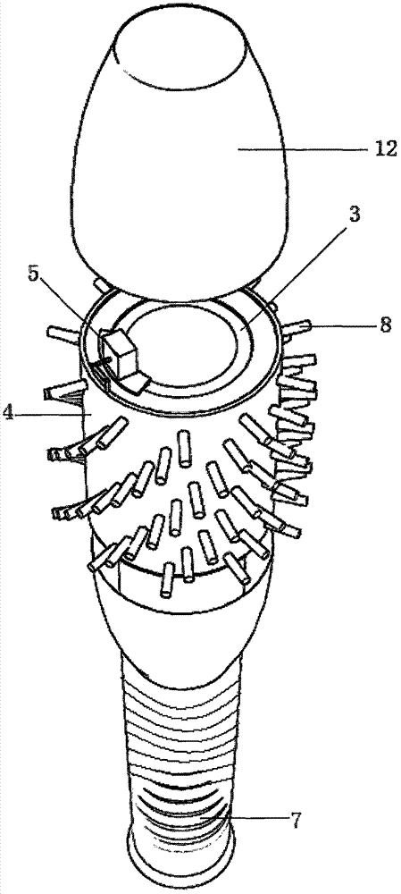
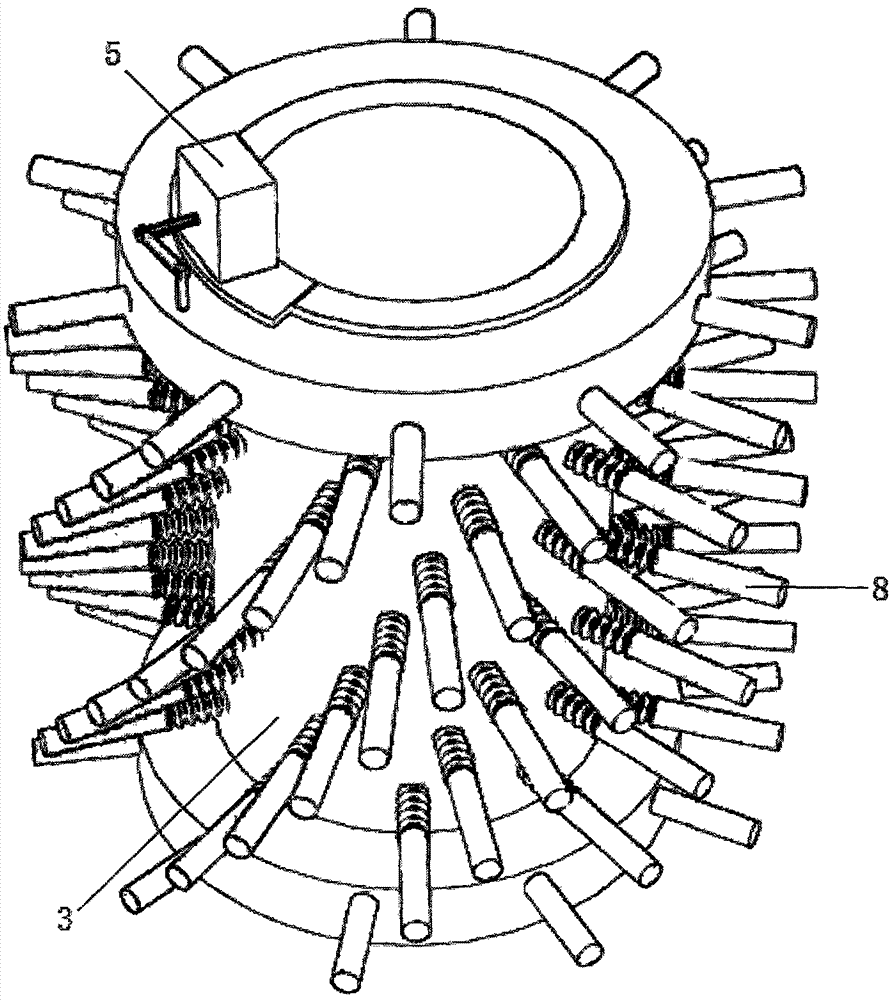
[0018] Such as Figure 1 to Figure 3 As shown, the spin type runoff fountain includes a base 1, a guide rod 2, and the lower end of the guide rod 2 is fixed to the base 1; a spin nozzle mechanism is installed on the guide rod 2; The shunt sleeve 3, the reversing sleeve 4, and the reversing steering gear 5 that are threaded; the shunting sleeve 3 is located inside the reversing sleeve 4 and is rotationally connected with the reversing sleeve 4; the reversing steering gear 5 is installed on the shunting sleeve 3, and the reversing The output end of the steering gear 5 is connected to the reversing sleeve 4; the shunt sleeve 3 is tubular, and the side wall of the shunt sleeve 3 in the circumferential direction is provided with an annular shunt chamber 6; the ring shunt chamber 6 communicates with the water supply pipe 7, and the water supply pipe 7 is a spring The upper end of the water supply pipe 7 is in rotation and sealing fit with the shunt sleeve 3; the outside of the side ...

Embodiment 2

[0021] Such as Figure 4 As shown, the difference between this embodiment and Embodiment 1 is that: the guide rod 2 of the spin-type runoff fountain is tubular; the inner wall of the guide rod 2 is provided with threads in the length direction; the guide rod 2 is provided with a positioning rotor; It includes an external casing 9 threadedly matched with the guide rod and an internal magnetic core rotor 10; the shunt sleeve 3 is slidably matched with the guide rod 2 and magnetically driven with the magnetic core rotor 10; the electric bayonet 11 is fixed on the casing 9; The output end of the pin 11 is clip-fitted with the magnetic core rotor 10 .

Embodiment 1

[0022] In Embodiment 1, the side wall of the guide rod 2 is provided with threads, and the shunt sleeve 3 is directly threaded with the guide rod 2. On the one hand, the rough surface of the guide rod 2 affects the viewing effect, and on the other hand, as long as the shunt sleeve 3 rotates, it will Lifting on the rod 2 cannot be fixed at a certain height to realize rotation alone. In this embodiment, the outer wall of the guide rod 2 is smooth, and the inner wall is provided with threads. The magnetic core rotor 10 inside the positioning rotor cooperates with the magnetic force of the shunt sleeve 3. When the shunt sleeve 3 rotates, the magnetic core rotor 10 can be driven to rotate, and the magnetic core rotor 10 After the electric bayonet pin 11 is relatively fixed to the shell 9, the shell 9 is driven to move and rotate. When the shell 9 rotates, the positioning rotor is raised and lowered along the screw thread, thereby dragging the spin nozzle mechanism to move up and dow...


PUM


Abstract

The invention discloses a spinning type runoff fountain, and relates to the technical field of garden molding equipment. The spinning type runoff fountain comprises a base and a guiding rod. The lower end of the guiding rod and the base are fixed. A spinning sprayer mechanism is arranged on the guiding rod. The spinning sprayer mechanism comprises a flow dividing sleeve, a reversing sleeve and a reversing steering engine, all of which are in rotating fit with the guiding rod. The flow dividing sleeve is located outside the reversing sleeve and is rotationally connected with the reversing sleeve. The reversing steering engine is arranged on the flow dividing sleeve, and the output end of the reversing steering engine is connected with the reversing sleeve. The flow dividing sleeve is in a tubular shape. An annular flow dividing cavity is formed in the side wall of the flow dividing sleeve in the circumferential direction and communicated with a water supply pipe. Spraying pipes are evenly distributed on the outer portion of the side wall of the flow dividing sleeve in the circumferential direction. The spraying pipes are in soft connection with the side wall and are communicated with the annular flow dividing cavity. The spraying pipes penetrate the side wall of the reversing sleeve and extend out of the reversing sleeve. The spinning type runoff fountain is ingenious in structure, rotates through reverse acting force of water flow and can be driven without an additional motor, control is simple, and the appearance is exquisite and attractive.

Description

technical field [0001] The invention relates to the technical field of garden modeling equipment. Background technique [0002] At present, although the existing fountain devices can produce rhythmic jumps with the music rhythm of the sound or directly with the rhythm of the external sound, and achieve a certain degree of appreciation through the combination of water and light and shadow, but the existing Fountain devices generally spray vertical or oblique fountains from a plurality of fixed spray holes, and the fountains have a single shape and poor agility. The revolving fountain represented by the publication number CN104384058A-a self-rotating multi-nozzle fountain, CN102527571A-a revolving fountain, CN201310151849-a revolving flying saucer fountain has been created on the diversity of fountains, improving the agility of fountains, However, the fountains cannot move up and down, and the range is limited, and the rotation of the fountains needs to be driven by another m...

Claims


Application Information

Patent Timeline
Patent Type & Authority Patents(China)
IPC IPC(8): B05B17/08
CPCB05B17/08B05B17/085
Inventor 邱汉周
Owner NINGDE NORMAL UNIV
Why Eureka
Try Eureka