Direct-boosting variable-excitation LC few-switching-tube switched reluctance generator converter system

A switched reluctance and switching tube technology, which is applied in the direction of controlling generators, controlling generators, and converting DC power input into DC power output through magnetic field changes, which can solve the problems of low cost performance, low utilization rate, and complex system. To achieve the effect of simplifying structure and control, improving reliability and high efficiency

Active Publication Date: 2020-01-24
CHINA JILIANG UNIV
View PDF6 Cites 0 Cited by
  • Summary
  • Abstract
  • Description
  • Claims
  • Application Information

AI Technical Summary

Problems solved by technology

[0005] We know that the power supply voltage required by the user end is often not directly output by the generator, and the electric energy directly sent by the generator needs to be boosted, which brings a large number of boosting devices and their control systems, making the whole system more complicated
[0006] In the field of switched reluctance generator systems, in view of the pursuit of maximum power output, low torque ripple, and high power generation efficiency, the original switching tube and low-speed excitation current control have shown that they cannot meet the increasingly high-end needs. Voltage as a variable is proposed to participate in the control, that is, variable excitation voltage control, so the first thing to face is the need to abandon the traditional variable current structure with uncontrollable excitation voltage such as secondary excitation of the battery or direct self-excitation, and develop a new type of variable excitation variable current. device
[0007] Among the existing switching reluctance generator converter devices, there is another problem of low utilization rate, that is, a large number of converter circuits are only put into use in extreme cases, and the cost performance is low

Method used


Image

  • Direct-boosting variable-excitation LC few-switching-tube switched reluctance generator converter system

Examples


Embodiment Construction

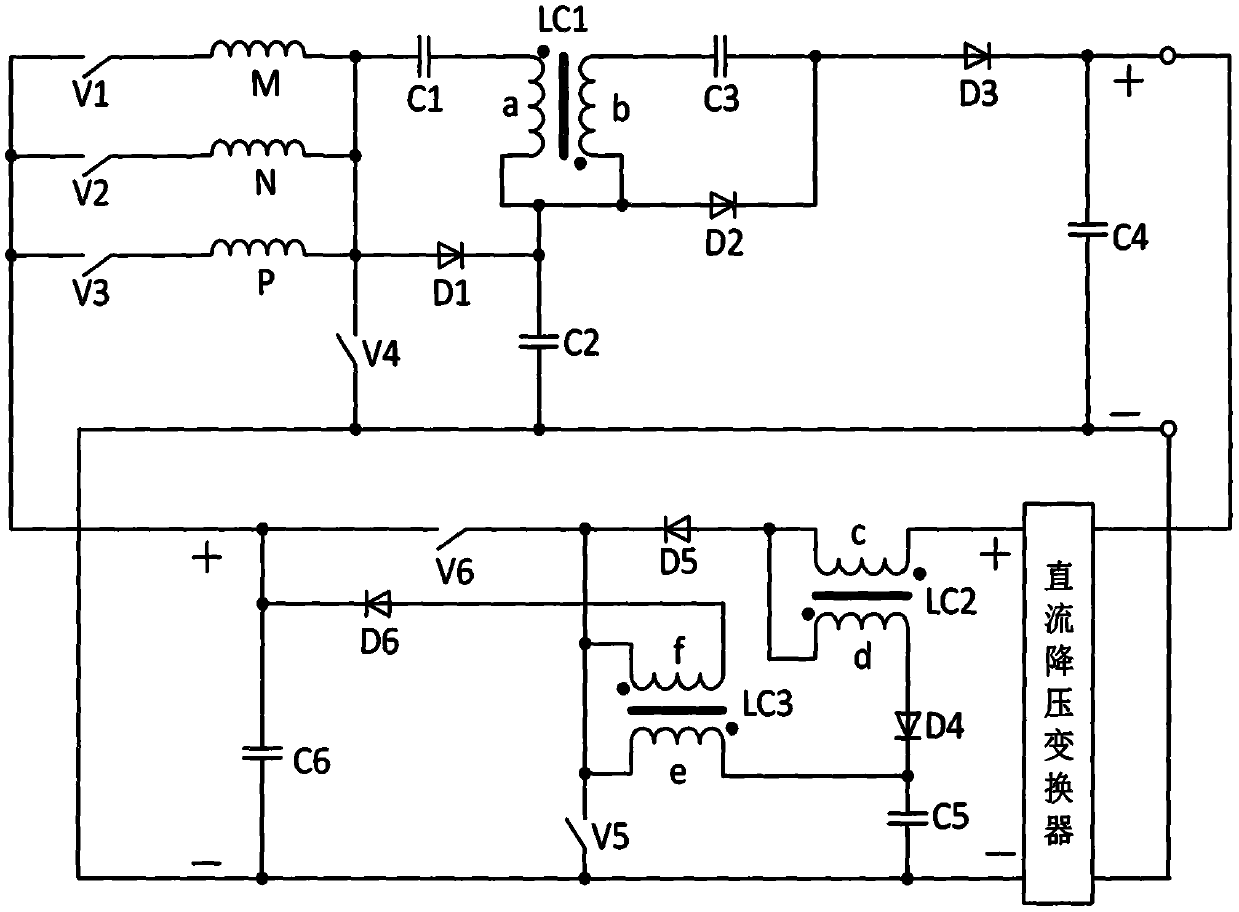
[0022] In this embodiment, the direct step-up voltage variable excitation LC less switching tube switched reluctance generator converter system, the circuit structure of the converter system is as attached figure 1 As shown, it consists of the first switching tube V1, the second switching tube V2, the third switching tube V3, the fourth switching tube V4, the fifth switching tube V5, the sixth switching tube V6, the first phase winding M, the second phase winding Winding N, third phase winding P, first capacitor C1, second capacitor C2, third capacitor C3, fourth capacitor C4, fifth capacitor C5, sixth capacitor C6, first diode D1, second diode Tube D2, third diode D3, fourth diode D4, fifth diode D5, sixth diode D6, first coupling reactor LC1, second coupling reactor LC2, third coupling reactor Composed of LC3 and DC step-down converter, the cathode of the first switching tube V1 is connected to one end of the first phase winding M, the cathode of the second switching tube V2...


PUM


Abstract

The invention discloses a direct-boosting variable-excitation LC few-switching-tube switched reluctance generator converter system, which comprises six switching tubes, a three-phase winding, six capacitors, six diodes, three coupling reactors and a direct-current buck converter. A first switching tube, a second switching tube, a third switching tube and a fourth switching tube are responsible forexcitation and power generation of each phase winding and are responsible for direct obtaining and outputting of a relatively high generation voltage. A fifth switching tube and a sixth switching tube are responsible for converting the excitation voltage and strengthening the excitation effect. Thus, direct boosting and variable excitation of the system are realized by at least five switching tubes, and high efficiency, high utilization rate and high reliability of the system are realized by effectively utilizing the capacitors and the reactors. The converter system is suitable for being applied to the field of high-speed medium-and-small-power switched reluctance generator systems driven by various kinds of power.

Description

technical field [0001] The invention relates to the field of switched reluctance motor systems, in particular to a switched reluctance generator converter system with direct step-up, variable excitation, high efficiency, high utilization rate and minimum switching tubes and a control method thereof. Background technique [0002] The advantages of the switched reluctance motor body in the motor industry are beyond doubt, and the position of the converter device in the switched reluctance motor system is decisive. [0003] In the switched reluctance motor converter system, the core component is the controllable switch tube. The existence of the switch tube has brought about a series of problems such as the microcomputer control system, control algorithm, switching loss and safety protection. Soft switching technology is indispensable in high-end applications, and the converter device relied on by the switched reluctance generator converter system is no exception. Fewer switchi...

Claims


Application Information

Patent Timeline
Patent Type & Authority Applications(China)
IPC IPC(8): H02P9/30H02P9/38H02M3/335
CPCH02M3/33569H02P9/305H02P9/38H02M1/0048Y02B70/10
Inventor 孙冠群蔡慧胡骁男
Owner CHINA JILIANG UNIV
Why Eureka
Try Eureka