Method for determining positional errors of drilled holes and securing the drilling process

An error and error calculation technology, applied in program control, general control systems, instruments, etc., can solve the problems of extra investment and operating costs of measuring machines, time staggering, etc., and achieve the effect of cheap setting or optimization

Active Publication Date: 2020-05-26
SIEB & MEYER
View PDF9 Cites 0 Cited by
  • Summary
  • Abstract
  • Description
  • Claims
  • Application Information

AI Technical Summary

Problems solved by technology

[0004] A disadvantage of this known device is that the determination of the positional error of the drilled hole in the printed circuit board is in most cases carried out at a significant time offset from the generation of the drilled hole and is carried out outside the processing machine.
Also to be considered is that measuring machines require additional capital and operating costs and also require trained personnel to operate the measuring machines

Method used


Image

  • Method for determining positional errors of drilled holes and securing the drilling process
  • Method for determining positional errors of drilled holes and securing the drilling process
  • Method for determining positional errors of drilled holes and securing the drilling process

Examples


Embodiment Construction

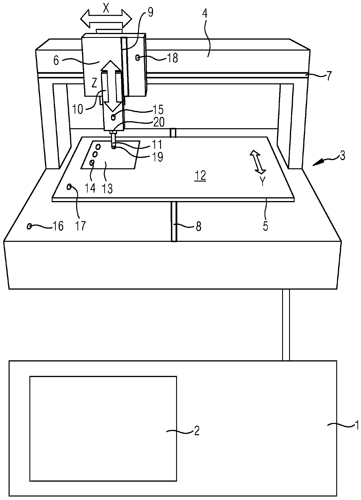
[0031] figure 1 A schematic structure according to the invention for determining a position error of a borehole is shown in a perspective view. A CNC controller 1 with a monitor 2 is connected to a circuit board drill 3 which has three linear drive axes 4, 5, 6, one for the X direction, one for the Y direction and one for the in the Z direction. Designs with more than 3 axes are also possible within the framework of the invention. Each of these drive shafts 4, 5, 6 has absolute measuring, linear displacement sensors 7, 8, 9 in the form of optically scanned steel scales, by means of which the individual drive shafts 4, 5 are detected , 6 the current position. Alternatively, optically scanning glass scales or magnetic length measuring systems can also be used within the framework of the invention. Furthermore, the circuit board drill 3 has a drill shaft 10 fastened to the drive shaft 6 in the Z direction. A drilling tool 11 is fastened in the drill shaft 10 . On the proces...


PUM


Abstract

In order to specify a method for determining positional errors of drilled holes (14) which are to be made in a workpiece (13) by means of a processing machine (3), which method is cost-effective and easy to handle and permits the user to determine, assess and optimise the production quality of drilled holes (14), it is proposed that during a positioning process of the processing machine (3) for producing a drilled hole (14), information from position encoders (7, 8, 9) of drive axles (4, 5, 6) is recorded by a control computer (1), from which information the control computer (1) of the processing machine (3) calculates and stores the positional errors of the drilled hole (14) at the moment of starting the drilled hole (14) as a difference between the SETPOINT position and the information of the position encoders (7, 8, 9).

Description

technical field [0001] The invention relates to a method for determining a position error of a bore hole produced in a workpiece with a processing machine. Background technique [0002] Position error is an important quality criterion when drilling printed circuit boards. When determining the position error of drilled holes, it should be noted that the position error should be determined as soon as possible after the drilled hole has been generated, so that defects can be quickly identified drilling, so that the number of possible rejects is kept as low as possible and possible faults of the processing machine can be quickly eliminated. [0003] A device and a method for determining positional errors of drilled holes in printed circuit boards are known from US Pat. No. 6,384,911 B1. The known device has an optical measuring scanner and a measuring-positioning table located below the scanner. A printed circuit board with previously drilled holes can be placed in the apparat...

Claims


Application Information

Patent Timeline
Patent Type & Authority Applications(China)
IPC IPC(8): G05B19/406H05K3/00
CPCG05B19/406G05B2219/37525G05B2219/37573G05B2219/37574G05B2219/49067H05K3/0047H05K2203/166
Inventor 托斯滕·坎珀
Owner SIEB & MEYER
Why Eureka
Try Eureka