Hoop bending machine

A hoop bending machine and bending mechanism technology, applied in the field of hoop bending machines, can solve the problems of reduced service life of the reducer, large moment of inertia of the reducer, inconvenient maintenance and replacement, etc., and achieve stable performance, small moment of inertia, and easy maintenance The effect of low cost of use

Inactive Publication Date: 2015-12-23
郑州市聚能建筑机械有限公司
View PDF9 Cites 11 Cited by
  • Summary
  • Abstract
  • Description
  • Claims
  • Application Information

AI Technical Summary

Problems solved by technology

However, the existing hoop bending machine cannot meet this requirement.
For example, the existing hoop bending machine adopts the traction mechanism and the bending mechanism are all driven by a reducer, but the reducer has a large moment of inertia, a slow response speed for high-speed start-stop and forward and reverse, and a large power loss. The service life of the reducer is reduced, it is easy to be damaged, and it is inconvenient to repair and replace. Moreover, the reducer has high cost, heavy weight, and large volume, resulting in a large overall size, increased weight and cost.

Method used


Image

  • Hoop bending machine
  • Hoop bending machine
  • Hoop bending machine

Examples


Embodiment 1

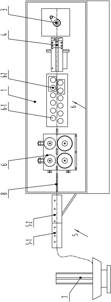
[0032] see figure 1 , in the figure, the hoop bending machine of the present invention includes a frame 1, and the frame is provided with a traction mechanism 2, a straightening mechanism, a bending mechanism 3 and a shearing mechanism 4, wherein the straightening mechanism has two groups, respectively front and rear straightening Mechanism 5 and up and down straightening mechanism 6, and front and rear straightening mechanism and up and down straightening mechanism are respectively placed on the two sides of traction mechanism, and pay-off frame 7 is arranged simultaneously before front and rear straightening mechanism. On the frame, a plurality of guide sleeves 8 are arranged along the moving direction; the front and rear straightening mechanisms and the upper and lower straightening mechanisms respectively include fixed wheel sets 5-1, 6-1 and adjusting wheel sets 5-2, 6-2.

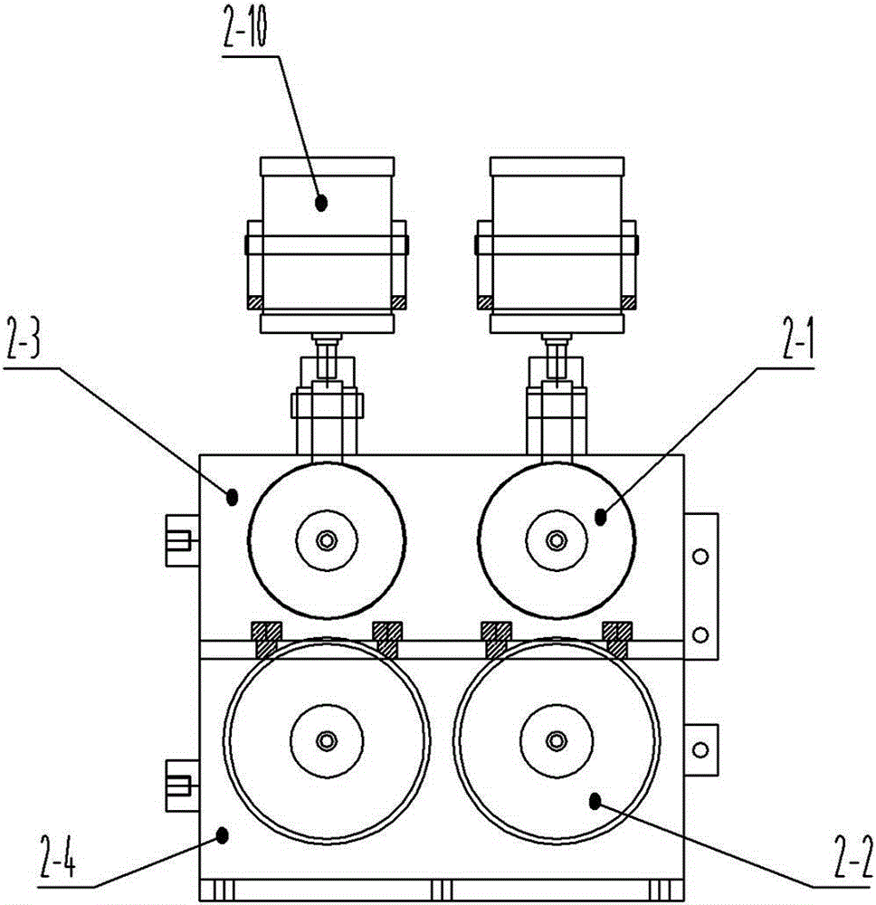
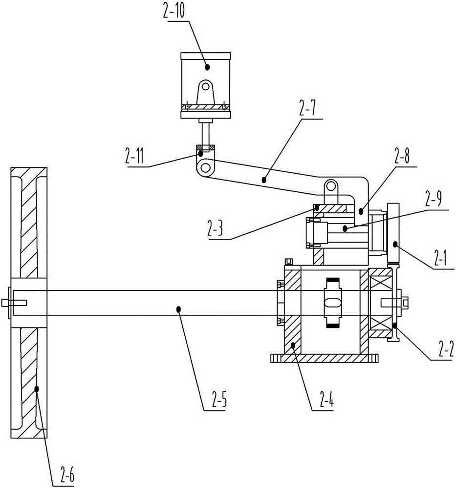
[0033] see Figure 2-3 , among the figures, the traction mechanism includes a pinch wheel set and ...


PUM


Abstract

The invention belongs to the technical field of steel bar hoop bending equipment, and particularly relates to a hoop bending machine. The hoop bending machine comprises a machine frame. The machine frame is provided with a drawing mechanism, two straightening mechanisms, a bending mechanism and a shearing mechanism. The straightening mechanisms comprise the front-back straightening mechanism and the top-bottom straightening mechanism, the front-back straightening mechanism and the top-bottom straightening mechanism are arranged on the two sides of the drawing mechanism respectively, and a pay-off rack is arranged in front of the front-back straightening mechanism. The drawing mechanism comprises a pressing wheel set, a drawing wheel set and supports, wherein the pressing wheel set and the drawing wheel set are arranged in parallel in the vertical direction in a matched mode, the end, where a driving drawing wheel of the drawing wheel set is located, of a drawing input shaft is connected with a synchronous belt drive mechanism, and a pressing mechanism is arranged corresponding to each pressing wheel. The bending mechanism comprises a case, a main shaft and a bending shaft, the main shaft is arranged in the case and connected to the synchronous belt drive mechanism, a central shaft is installed at one end of the main shaft, a bending sleeve is arranged between the main shaft and the case in a sleeving mode, and the bending shaft is arranged on the side, close to the central shaft, of the bending sleeve. The hoop bending machine is high in automation degree, high in response speed of high speed start and stop and forward and reverse rotation, short in machining cycle and low in cost.

Description

technical field [0001] The invention belongs to the technical field of steel bar hoop bending equipment, in particular to a hoop bending machine. Background technique [0002] With the rapid development of economic construction, hoop bending machine has been widely used. The hoop bending machine in the prior art includes a traction mechanism, a straightening mechanism, a bending mechanism and a shearing mechanism. With the continuous improvement of technical requirements, higher requirements are put forward for the hoop bending machine to achieve high-speed, accurate, frequent start-stop and positive and negative positioning. But existing hoop bending machine can't satisfy this requirement. For example, the existing hoop bending machine adopts the traction mechanism and the bending mechanism are all driven by a reducer, but the reducer has a large moment of inertia, a slow response speed for high-speed start-stop and forward and reverse, and a large power loss. The servic...

Claims


Application Information

Patent Timeline
Patent Type & Authority Applications(China)
IPC IPC(8): B21F1/00B21F11/00B21F23/00
Inventor 梁亮
Owner 郑州市聚能建筑机械有限公司
Why Eureka
Try Eureka