Tool device for fixing small machined end of conical sleeve

A technology of tapered sleeves and tooling, which is applied in the direction of expanding the mandrel, etc., which can solve the problems of high cost of use, easy distortion and cracking of copper tapered sleeves, and achieve the effect of avoiding distortion

Inactive Publication Date: 2015-12-23
CHONGQING YUEHONG MACHINERY PLANT
View PDF0 Cites 0 Cited by
  • Summary
  • Abstract
  • Description
  • Claims
  • Application Information

AI Technical Summary

Problems solved by technology

[0002] At present, the processing of tapered sleeves is more common on machine tools. In the metallurgical steelmaking industry, there is a copper tapered sleeve that is prone to cracking when used at high temperatures. If it is discarded, the cost of use will be high. Repair welding is often used for repair. Finishing after repair
[0003] In the current technology, when the copper taper sleeve is finished, the large end of the copper taper sleeve is clamped by the chuck of the lathe, and the small end of the copper taper sleeve is often not fixed. When the sleeve is twisted, the collet is often clamped tightly to the large end of the copper taper sleeve, which is easy to pinch the large end of the copper taper sleeve; in order not to pinch the large end of the copper taper sleeve, when turning the outer circle of the copper The copper taper sleeve is prone to distortion, resulting in low machining accuracy

Method used


Image

  • Tool device for fixing small machined end of conical sleeve
  • Tool device for fixing small machined end of conical sleeve
  • Tool device for fixing small machined end of conical sleeve

Examples


Embodiment Construction

[0014] The present invention will be described in further detail below in conjunction with the accompanying drawings and specific embodiments.

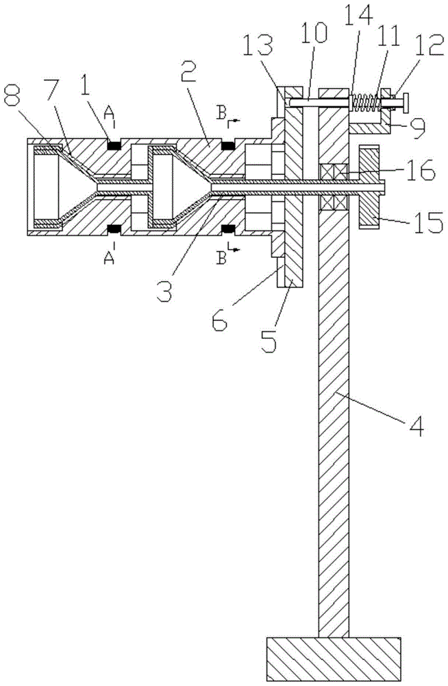
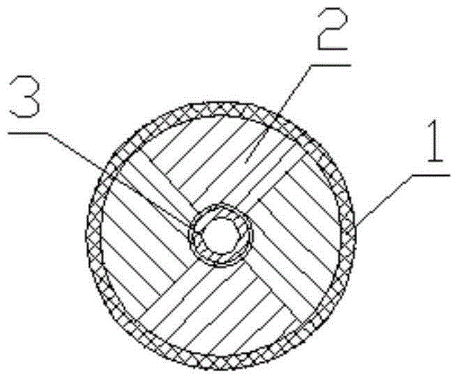
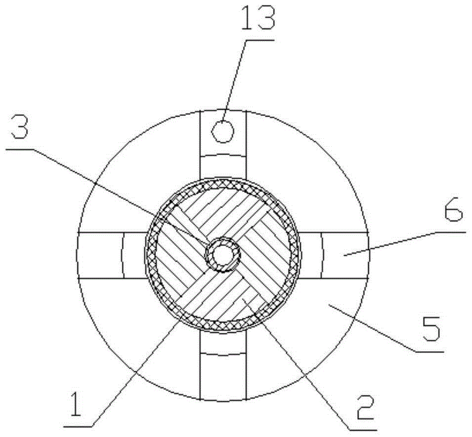
[0015] Such as Figures 1 to 3 As shown, a tooling device for fixing the small end of the tapered sleeve, including an elastic sleeve 1, an expansion body 2, a driving rod 3, a support frame 4, a limit block 5 arranged at one end of the expansion body 2, a bracket 9, a screw rod 10, Spring 11 and lock nut 12. The outer surface of the expansion body 2 is provided with at least two annular grooves along its circumferential direction. In this embodiment, the expansion body 2 is provided with two annular grooves, and the elastic sleeve 1 is set in the annular grooves. The limiting block 5 is a plate-shaped structure, the limiting block 5 is radially provided with chute 6, and the cross section of the expansion body 2 is a valve ring structure with at least three petals. One end of the valve annulus of the ring structure is set in the sl...


PUM


Abstract

The invention discloses a tool device for fixing the small machined end of a conical sleeve. The tool device comprises elastic sleeves, an expanding body, a driving rod, a supporting frame, a limiting block, a support, a screw, a spring and a locking nut. The elastic sleeves are sleeved with annular grooves in the expanding body. A sliding groove is formed in the limiting block in the radial direction, one end of the expanding body is arranged in the sliding groove in the manner of being capable of sliding in the radial direction, and the driving rod is arranged in the expanding body in the axial direction. Taper structures are arranged at the inner circle of the expanding body in the axial direction, and cones are arranged at the outer circle of the driving rod. A first through hole is formed in the top of the limiting block. The support is fixedly arranged on the supporting frame, and a second through hole is formed in the top of the supporting frame. The screw penetrates a third through hole of the support, one end of the screw penetrates the second through hole and corresponds to the first through hole, and the spring is located between the support and a circular truncated cone arranged on the screw. The small end of the conical sleeve can be located through the tool device, the big end of the conical sleeve does not need to be clamped through a chuck of a lathe in an excessively-tight manner and is prevented from being broken by clamping, and it is also avoided that distortion is generated when the outer circle of the conical sleeve is turned.

Description

technical field [0001] The invention relates to a machining positioning device, in particular to a tooling device for fixing the machining small end of a tapered sleeve. Background technique [0002] At present, the processing of tapered sleeves is more common on machine tools. In the metallurgical steelmaking industry, there is a copper tapered sleeve that is prone to cracking when used at high temperatures. If it is discarded, the cost of use will be high. Repair welding is often used for repair. Finishing after restoration. [0003] In the current technology, when the copper taper sleeve is finished, the large end of the copper taper sleeve is clamped by the chuck of the lathe, and the small end of the copper taper sleeve is often not fixed. When the sleeve is twisted, the collet is often clamped tightly to the large end of the copper taper sleeve, which is easy to pinch the large end of the copper taper sleeve; in order not to pinch the large end of the copper taper sle...

Claims


Application Information

Patent Timeline
IPC IPC(8): B23B31/40
CPCB23B31/406
Inventor 伍波
Owner CHONGQING YUEHONG MACHINERY PLANT
Why Eureka
Try Eureka