Mechanically clamped type fir tree blade-root milling cutter

A clip-on, fungus-type technology, applied in the direction of milling cutters, milling machine equipment, manufacturing tools, etc., can solve the problems of reduced use cost, inability to use general-purpose blades, and increased manufacturing costs of blades to achieve effective and stable processing and reduce Effect of Vibration and Roughness Improvement

Active Publication Date: 2015-12-23
DONGFANG TURBINE CO LTD
View PDF11 Cites 2 Cited by
  • Summary
  • Abstract
  • Description
  • Claims
  • Application Information

AI Technical Summary

Problems solved by technology

[0002] In the process of producing steam turbine blades, in order to install the steam turbine blade root, a fungus-shaped groove is formed on the outer ring of the rotor. The fungal-shaped blade root blade is installed on the outer ring groove to form a first-stage blade. Side-mounted clip-on structure, so the cost of cutting tools is greatly reduced, but because the shape of the blade is matched according to the fungus type line, it is not possible to use general-purpose blades on the market, which increases the manufacturing cost of the blade

Method used


Image

  • Mechanically clamped type fir tree blade-root milling cutter
  • Mechanically clamped type fir tree blade-root milling cutter
  • Mechanically clamped type fir tree blade-root milling cutter

Examples


Embodiment Construction

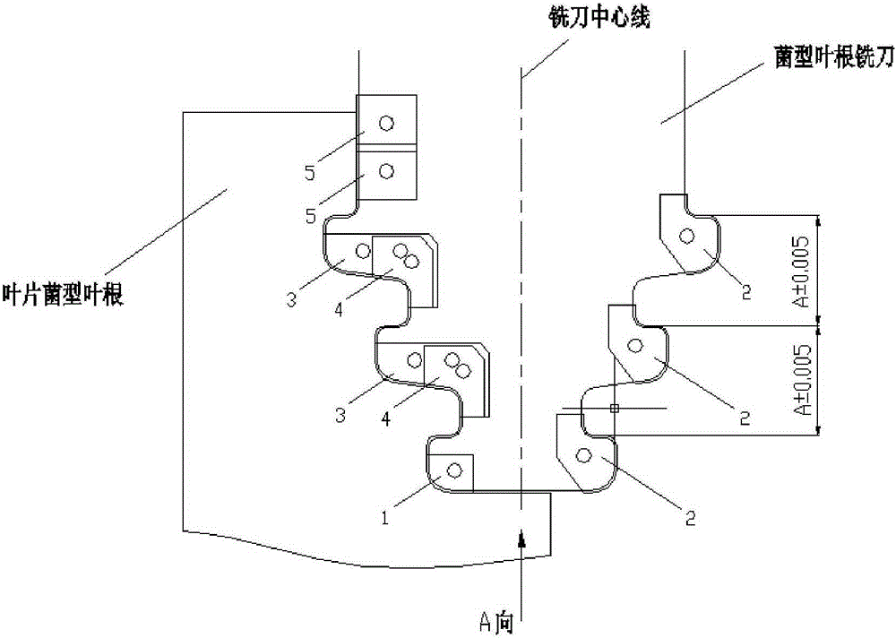
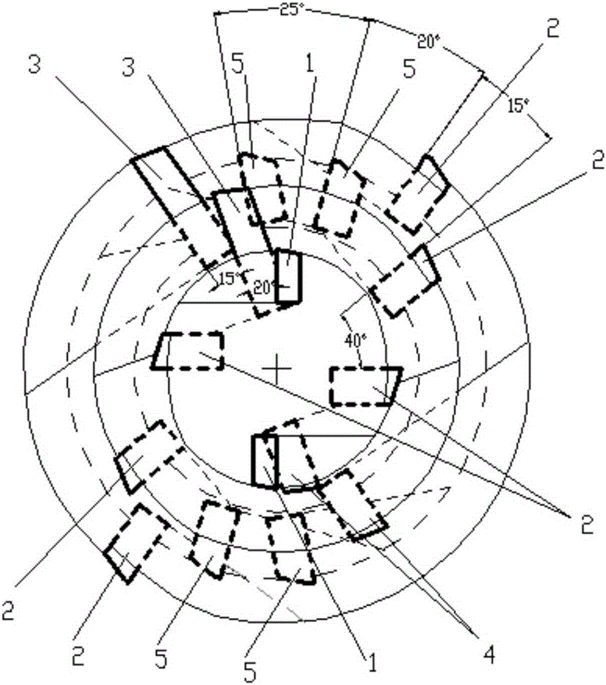
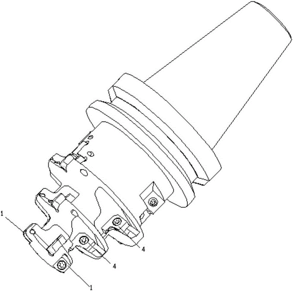
[0012] A kind of machine-clip fungus-type leaf root milling cutter, such as Figure 1 to Figure 5 As shown, including: No. 1 blade 1, No. 2 blade 2, No. 3 blade 3, No. 4 blade 4 and No. 5 blade 5, etc. The specific setting positions and angles of the blades in the cutter body are as follows:

[0013] Two No. 1 blades 1 are arranged in the first row of blade grooves, and they are symmetrically distributed about the center. No. blades are end face blades, which are used to process end faces;

[0014] Two No. 2 blades 2 are arranged in the second row of sipes, symmetrically distributed about the center, and the blade profile is taken from the theoretical contour profile of the fungus leaf root, and the included angle with the No. 1 blade is 90°, and the rake angle is 0°. The surface is evenly passed through the center;

[0015] The No. 3 blade 3 and the No. 4 blade 4 are arranged in the third row of sipes, which are distributed symmetrically about the center and arranged in a s...


PUM


Abstract

The invention discloses a mechanically clamped fir tree blade-root milling cutter. The mechanically clamped fir tree blade-root milling cutter comprises a fir tree shaped cutter body and eight rows of cutter grooves which are arranged in the cutter body, wherein two first cutter blades which are symmetrically distributed with respect to the center are arranged in the first row of cutter grooves starting with the end surface, the front cutter surfaces of the first cutter blades pass through the center, and the front angles of the first cutter blades are 0 degrees; two second cutter blades which are symmetrically distributed with respect to the center are arranged in each of the second row of cutter grooves, the fourth row of cutter grooves and the sixth row of cutter grooves, the front cutter surfaces of the second cutter blades pass through the center, and the front angles of the second cutter blades are 0 degrees; third cutter blades and fourth cutter blades which are symmetrically distributed with respect to the center are arranged in the third row of cutter grooves and the fifth row of cutter grooves; and two fifth cutter blades which are symmetrically distributed with respect to the center are arranged in each of the seventh row of cutter grooves and the eighth row of cutter grooves, and the front cutter surfaces of the fifth cutter blades pass through the center, and the front angles of the fifth cutter blades are 0 degrees. The mechanically clamped fir tree blade-root milling cutter has the advantages that the quantity of the cutter blades is reduced on the premise of realizing a complete processing profile and considering specialized processing sites, and the rigidity and strength of the cutter body are ensured to the greatest extent, thereby providing a guarantee for the rigidity of the cutter in a processing process and reducing the vibration stripes of the cutter generated due to vibration.

Description

technical field [0001] The invention belongs to the technical field of processing steam turbine blade fungus-shaped blade roots, and in particular relates to a machine clip-type fungus-shaped blade root milling cutter. Background technique [0002] In the process of producing steam turbine blades, in order to install the steam turbine blade root, a fungus-shaped groove is formed on the outer ring of the rotor. The fungal-shaped blade root blade is installed on the outer ring groove to form a first-stage blade. The side-mounted machine clip structure greatly reduces the cost of the tool, but because the shape of the blade is matched according to the fungus type line, the general blade on the market cannot be used, so the manufacturing cost of the blade increases. Contents of the invention [0003] In order to overcome the disadvantages of the prior art, the present invention provides a machine-clip fungus type leaf root milling cutter. [0004] The technical solution adopt...

Claims


Application Information

Patent Timeline
Patent Type & Authority Applications(China)
IPC IPC(8): B23C5/02
Inventor 王强刘文泽谢鸿周乐安贠庆芳张轶
Owner DONGFANG TURBINE CO LTD
Why Eureka
Try Eureka