
A profile heating device

A technology for heating equipment and profiles, applied in the field of metallurgy, can solve the problems of poor continuity and insufficient uniformity of workpieces, and achieve the effects of easy control of moving speed, stable transmission and convenient transportation.

Active Publication Date: 2017-12-12
南通莱特伟特汽配科技有限公司
View PDF1 Cites 0 Cited by
  • Summary
  • Abstract
  • Description
  • Claims
  • Application Information

AI Technical Summary

Problems solved by technology

[0003] The workpieces treated by the above-mentioned heat treatment furnace are not continuous and uniform enough, so it is necessary to improve

Method used


Image

  • A profile heating device
  • A profile heating device
  • A profile heating device

Examples


Embodiment Construction

[0033] The following descriptions are only preferred embodiments of the present invention, and therefore do not limit the protection scope of the present invention.

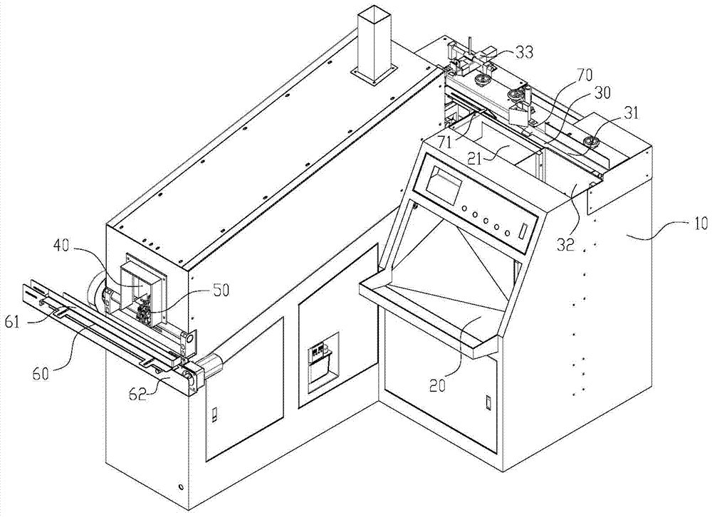
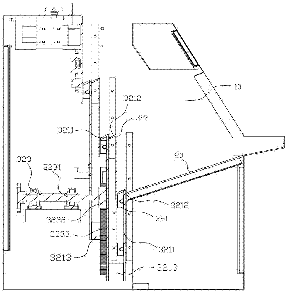
[0034] Examples, see Figure 1 to Figure 5 Shown: a profile heating equipment, including: a body 10, a hopper 20 is installed on the body 10, a large number of cylindrical workpieces are placed in the hopper 20, and the workpieces can also be other elongated workpieces; a conveying mechanism 30, The conveying mechanism 30 is arranged on the body 10 and can transport the workpiece in the hopper 20; the heating channel 40, the heating channel 40 is installed on the body 10, and the transmission chain 50 and the sprocket wheel 52 that drives the transmission chain 50 to rotate are installed in the heating channel 40 , the transmission chain 50 is composed of several sprockets 51 and hinge pins that link the sprockets 51 to form a closed loop, and a slot 515 is formed between two adjacent sprockets 51; the conveying ...


PUM


Abstract

The invention discloses a profile heating device. The profile heating device comprises a machine body, a conveying mechanism and a heating passageway. A hopper is arranged on the machine body. Conical workpieces are placed in the hopper. The conveying mechanism is arranged on the machine body and conveys the workpieces in the hopper. The heating passageway is arranged on the machine body. A transmission chain and a chain wheel driving the transmission chain to rotate are arranged in the heating passageway. The transmission chain is a closed ring composed of a plurality of chain teeth and rotating shaft pins through which the chain teeth are hinged and connected. Clamping grooves are formed between the adjacent chain teeth. The conveying mechanism conveys and pushes the workpieces to the transmission chain. The workpieces fall into the clamping grooves and move in the heating passageway along with the transmission chain. The profile heating device has the beneficial effects of being good in connecting, machining and thermal treating effect.

Description

technical field [0001] The invention relates to the technical field of metallurgy, in particular to profile heating equipment. Background technique [0002] Chinese patent CN102851462A discloses a heat treatment furnace, which belongs to the technical field of furnace facilities. Including the furnace rack; the furnace body arranged on the furnace rack, the bottom of both sides of the furnace are recessed downwards with grooves, and the workpiece carrier frames are fixed in the length direction of the grooves, and a set of top columns are set at the bottom of the grooves to allow bit cavity; body, corresponding to the bottom of the furnace body; traction trolley lifting mechanism, installed above the body; trolley guide rail frame, fixedly connected with traction trolley lifting mechanism; traction trolley, arranged on the trolley guide rail frame, at the length of traction trolley A set of jacking columns are fixed on both sides of the direction, and each jacking column is...

Claims


Application Information

Patent Timeline
Patent Type & Authority Patents(China)
IPC IPC(8): C21D9/00
Inventor 杨涛蒋定安
Owner 南通莱特伟特汽配科技有限公司
Learn More