Test pile and working method thereof

A technology of test piles and test strips, which is applied in the field of test piles for detecting the state of cathodic protection of pipelines. It can solve problems affecting the working efficiency of cathodic protection potential of pipelines, difficulties for operators to reach the site, and influence on the measurement accuracy of polarization potentials, etc., so as to increase the calibration Accuracy, simple installation and layout, easy replacement and maintenance

Active Publication Date: 2015-12-23
QINGDAO YAHE SCI & TECH DEV
View PDF5 Cites 1 Cited by
  • Summary
  • Abstract
  • Description
  • Claims
  • Application Information

AI Technical Summary

Problems solved by technology

However, the test pile is generally set in a remote location along with the pipeline, and it is very difficult for the operator to reach the site. After the last test is completed, the operator tends to forget to close the switch, so that the test piece will not be polarized when it arrives at the site next time. , and cannot be detected, even if the switch is closed immediately after arriving at the site, it will take several hours for the test piece to be fully polarized. The operation error of forgetting to close the switch in the last detection will seriously affect the cathodic protection potential detection of the entire pipeline If the polarization is not sufficient, it will also affect the measurement accuracy of the polarization potential

Method used


Image

  • Test pile and working method thereof
  • Test pile and working method thereof
  • Test pile and working method thereof

Examples


Embodiment 1

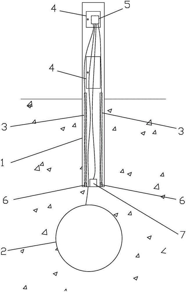
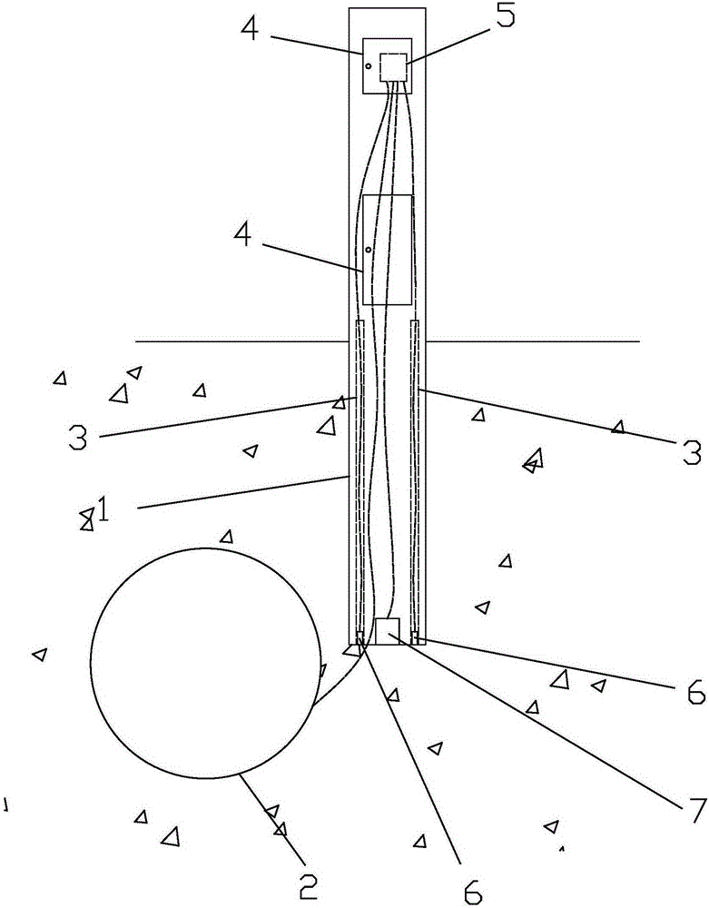
[0043] Such as figure 1 and figure 2 As shown, the test pile includes a hollow pile body 1, the pile body 1 is made of insulating material or other materials that have been insulated, the lower part of the pile body 1 is located underground, and the pile body 1 is located above or on the side of the underground pipeline 2 .

[0044] A test piece tube 3 is installed on the pile body 1 inner wall, and the test piece tube 3 is also made of insulating material or other materials through insulating treatment, and the bottom end of the test piece tube 3 is flush with the opening provided at the bottom end of the pile body 1 .

[0045] The pile body 1 is provided with a hatch 4, at least one hatch 4 is provided, and the lower edge of the hatch 4 is higher than the top of the test piece tube 3 and also higher than the ground, meeting the industry requirements for cathodic protection calibration operations.

[0046]A wiring board 5 is installed in the pile body 1, and the wiring boa...

Embodiment 2

[0051] The structure of embodiment two is basically the same as that of embodiment one, the difference is:

[0052] Such as figure 1 As shown, two cabin doors 4 are provided, including a measuring door arranged above and an inspection door arranged below. The measuring door is aligned with the wiring board 3 so that the detection equipment can be connected with the wiring board 3 through the measuring door. The access door is used to send the calibrated working electrode into the pile body 1, and at the same time, the test piece 6 and the reference electrode 7 can be taken out from the ground through the access door.

Embodiment 3

[0054] The structure of embodiment three is basically the same as that of embodiment one, the difference is:

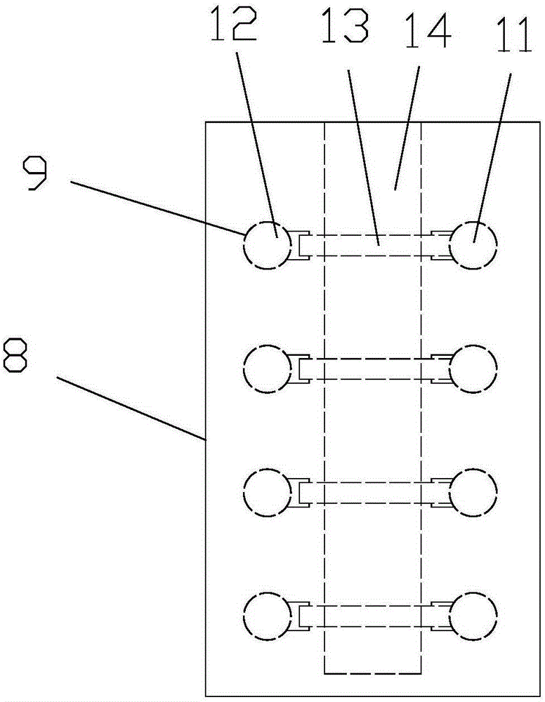
[0055] Such as image 3 As shown, the wiring board 5 includes a housing 8 in which a wiring switch 9 is installed.

[0056] The wiring switch 9 includes a main connector 11 and a secondary connector 12. The primary connector 11 and the secondary connector 12 are connected by an elastic metal sheet 13.

[0057] The housing 8 is provided with a socket 14 , the elastic metal sheet 13 of the wiring switch 9 is aligned with the socket 14 , and the wiring board 5 is connected with a detection plug that can be inserted into the socket 14 .

[0058] The test piece 6 includes a polarized test piece, and a plurality of connection switches 9 are provided, including a pipeline connection switch, a reference electrode connection switch and a polarization test piece connection switch.

[0059] The main joint 11 of the pipeline wiring switch is electrically connected to the pipeli...


PUM


Abstract

A test pile comprises a hollow pile body. The lower portion of the pile body is located underground, and the pile body is located above or beside an underground pipeline. A test block pipe is installed in the pile body. A cabin door is arranged on the pile body. A wiring board is installed in the pile body. A test block is installed in the test block pipe. A reference electrode is installed in the pile body. The test block, the reference electrode and the pipeline are connected with the wiring board. The lower portion of the test pile is inserted underground, the test block is installed in the test block pipe, the reference electrode is installed in the lower end of the test pile, and therefore the lower portion of the test pile can be used as a reference pipe, and it is unnecessary to additionally install a reference pipe; installation and layout are simple, and the cost of whole pipeline cathode protection engineering is also reduced. When the reference electrode is calibrated, a working electrode for calibration can be conveyed to an underground position through the test pile, the working electrode is made to be close to the reference electrode to be calibrated as much as possible, and calibration is more accurate; the reference electrode to be calibrated can also be taken out to an overground position from the underground position along an inner cavity of the test pile, the reference electrode directly gets close to the working electrode on the ground, calibration is conducted, and therefore calibration accuracy is improved; moreover, the reference electrode and the test block can be taken out from the underground position and are convenient to replace and maintain.

Description

technical field [0001] The invention relates to the technical field of cathodic protection, in particular to a test pile for detecting the cathodic protection state of pipelines and a working method thereof. Background technique [0002] The test pile is mainly used for pipeline potential detection and detection of cathodic protection system protection effect of metal structures such as large steel structure storage tanks and pipelines. In order to improve the detection accuracy and eliminate the IR drop, the test pile passes through the switch and the set test piece and reference electrode to detect the polarization potential of the pipeline. In order to ensure the accuracy of polarization potential detection, it is necessary to calibrate the reference electrode regularly. There are two main ways to calibrate the reference electrode: one is to directly use the portable reference electrode as the reference electrode and place it on the ground. Calibrate the reference electr...

Claims


Application Information

Patent Timeline
Patent Type & Authority Applications(China)
IPC IPC(8): C23F13/22
Inventor 仲维滨孙勤王红军
Owner QINGDAO YAHE SCI & TECH DEV
Why Eureka
Try Eureka