
Quick formwork erecting construction method for cast-in-place wave wall

A construction method and technology of a wave wall, applied in the direction of breakwaters, coastline protection, jetties, etc., can solve the problems of increasing project investment and labor intensity of workers, increasing invalid construction time, and large safety hazards of scaffolding, so as to save linear construction period and reduce The labor intensity of workers and the effect of shortening the construction period of the project

Inactive Publication Date: 2015-12-23
SINOHYDRO BUREAU 7 CO LTD
View PDF7 Cites 13 Cited by
  • Summary
  • Abstract
  • Description
  • Claims
  • Application Information

AI Technical Summary

Problems solved by technology

The formwork is generally assembled with small formwork or large formwork. By reinforcing the tie rods, scaffolding needs to be erected at the same time. After one section is poured, the formwork and scaffolding are removed and then the next section is assembled. Formwork erection, pouring, formwork removal, scaffolding removal, formwork assembly and scaffolding erection greatly increase the ineffective construction time, thus causing problems such as long construction period, large resource investment and high cost, greatly reducing work efficiency, increasing engineering investment and worker labor Intensity, resulting in low efficiency and long construction period. At the same time, the use of scaffolding has relatively large safety hazards, especially when the upstream surface is on the dam slope, it is difficult to operate
Moreover, the formwork reinforcement quality is poor, the formwork joints are many, the rigidity is weak, and the quality of concrete cannot be guaranteed

Method used


Image

  • Quick formwork erecting construction method for cast-in-place wave wall
  • Quick formwork erecting construction method for cast-in-place wave wall
  • Quick formwork erecting construction method for cast-in-place wave wall

Examples


Embodiment Construction

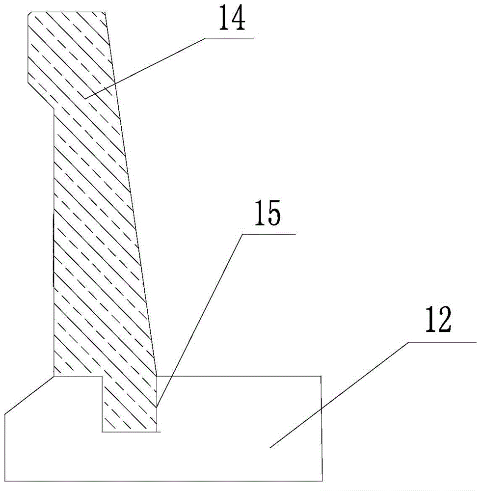
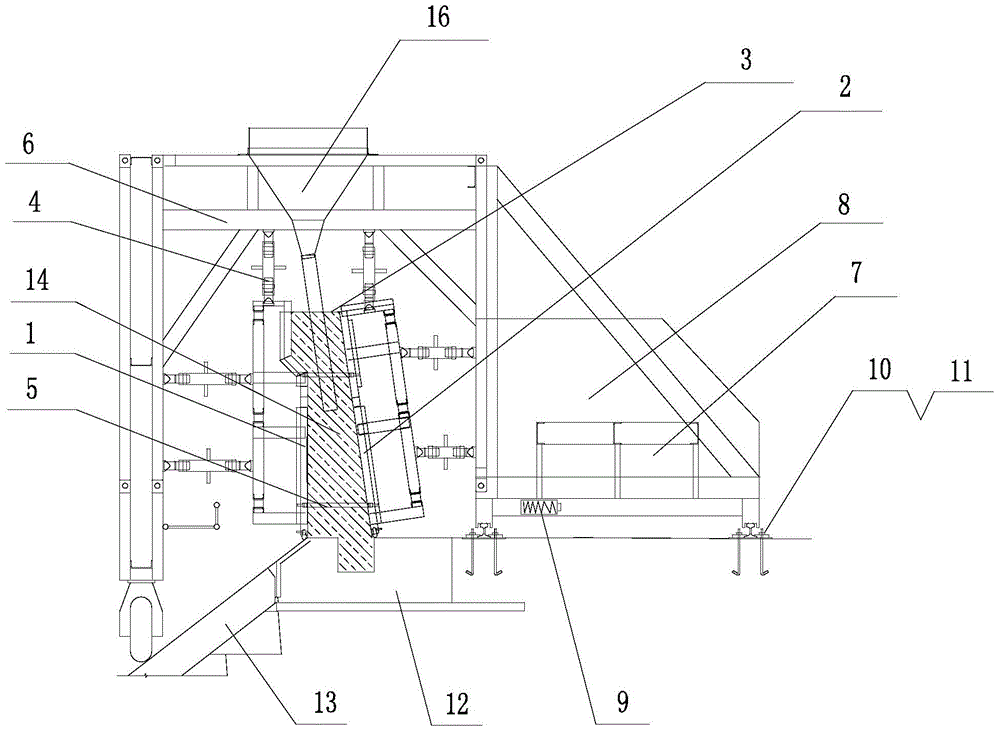
[0034] The present invention uses a special pouring device "self-propelled hydraulic cantilever gantry type anti-wave wall concrete pouring device (patent application number CN201020648386)" to fully and quickly perform formwork and demolition of the anti-wave wall pouring, refer to figure 1 , the pouring device consists of a trolley, traction device, shaped formwork system and support system. The trolley includes a door frame 6, screw rod braces, an operating platform, a counterweight platform 8 and a walking mechanism. The shaped formwork system is based on the concrete pouring structure. It is determined that it is composed of upstream side formwork 1, downstream side formwork 2 and end formwork 3, and is suspended and connected to the door frame 6 through hydraulic support rods 4, and the electric hoist 9 of the traction device is installed under the front edge of the counterweight platform 8 . The counterweight platform 8 is provided with concrete counterweight blocks 7 ,...


PUM

PropertyMeasurementUnit
Lengthaaaaaaaaaa

Abstract

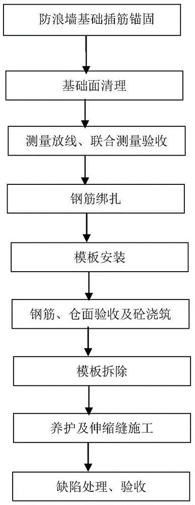
The invention provides a quick formwork erecting construction method for a cast-in-place wave wall. According to the method, a base of the wave wall is cast and then a special casting device is used for erecting a formwork for a wall body and casting the wall body. The method includes the following steps that firstly, insertion ribs are anchored to the cast base; secondly, a foundation face is cleaned; thirdly, a measuring line is released out of a start pile of a branch bin of the wave wall body; fourthly, a bound reinforcing steel bar net of the wave wall body is fixed to the anchored insertion ribs; fifthly, the formwork is installed through a shaping formwork system of the special casting device; sixthly, the wave wall body is cast through a sequential construction method; seventhly, the formwork is detached; eighthly, a curing agent is sprayed after the formwork is detached; and ninthly, defects are repaired. By the adoption of the method, the formwork installation procedure is simplified, the problems that a formwork supporting system can hardly be erected on the upstream face and a working face is not available are solved, operation is easy and convenient, the concrete quality is good, concrete sequential construction is performed, an engineering construction period is shortened, engineering cost is reduced, the labor intensity of workers is relieved, and potential safety hazards are eliminated.

Description

Technical field: [0001] The invention relates to the technical field of water conservancy engineering, in particular to the construction technology of face rockfill dams on the left and right banks and clay core wall dam crest anti-wave walls in river courses and water conservancy projects. Construction method. Background technique: [0002] The anti-wave wall is a water-retaining structure installed at the front of the dam crest to prevent waves from crossing the dam crest. It is mostly used on reservoirs, rivers, and dams to prevent waves, floods, and water. [0003] At present, prefabricated reinforced concrete columns and prefabricated concrete slabs and other prefabricated components are used to construct the wave wall of the face rockfill dam crest of the water conservancy project. Although the construction process is simple, it is prefabricated in advance, the installation on site is quick, and the construction period is short, but the seismic performance of the pref...

Claims


Application Information

Patent Timeline
IPC IPC(8): E02B3/06
Inventor 伍夕国易世森曾永智
Owner SINOHYDRO BUREAU 7 CO LTD
Learn More