Composite retaining structure of foundation pit project and construction method thereof

A technology of enclosure structure and construction method, which can be applied in basic structure engineering, excavation, construction, etc., can solve the problems of enclosure structure deformation and pit bottom uplift, etc. Effect

Inactive Publication Date: 2015-12-23
SHANGHAI NO 7 CONSTR
View PDF7 Cites 12 Cited by
  • Summary
  • Abstract
  • Description
  • Claims
  • Application Information

AI Technical Summary

Problems solved by technology

[0005] In view of the fact that the existing underground diaphragm wall enclosure structure has been implemented, in order to increase the utilization rate of the underground space and increase the excavation depth, if no corresponding reinforcement measures are taken, it will lead to the deformation of the original enclosure structure and the uplift of the pit bottom. problem, the object of the present invention is to provide a composite enclosure structure for foundation pit engineering and its construction method, which uses the composite enclosure structure combined with underground diaphragm wall and bored pile to increase its depth of penetration and lateral rigidity, and by adding downturned corbels and post-cast belts on the foundation floor, the support replacement of the ring beam and reinforced concrete support before removal was completed, thereby ensuring the construction safety of the foundation pit and effectively controlling the depth of the foundation pit. out of shape

Method used


Image

  • Composite retaining structure of foundation pit project and construction method thereof
  • Composite retaining structure of foundation pit project and construction method thereof
  • Composite retaining structure of foundation pit project and construction method thereof

Examples


Embodiment 1

[0023] Embodiment 1: In this embodiment, the floor area is 16,400 m 2 Taking the construction of a certain foundation pit project as an example, the foundation pit was excavated according to the design depth of the two underground floors and the underground diaphragm wall was constructed. After that, according to the owner's requirements, the two underground floors were adjusted to three underground floors to improve the utilization of underground space Therefore, it is necessary to carry out effective reinforcement design and construction on the original underground enclosure structure to meet the requirements of the construction code, combined with the following Figure 1 to Figure 8 Illustrate the construction method of the compound enclosure structure of foundation pit project of this embodiment, concrete steps are as follows:

[0024] 1. In order to meet the requirements of excavation for foundation pit safety and environmental protection, such as figure 1 As shown, alon...

Embodiment 2

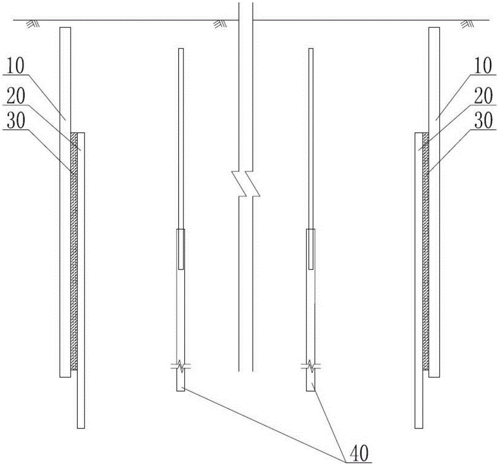
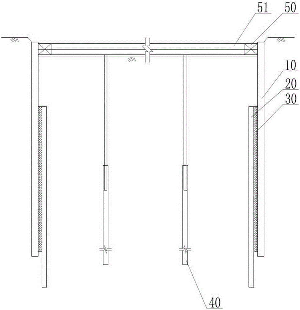
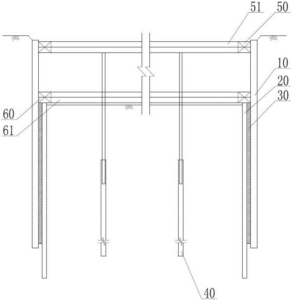
[0031] Embodiment 2: Combination Figure 9 and Figure 10 The composite enclosure structure of the foundation pit project of present embodiment is illustrated, and it comprises the underground diaphragm wall 10 that is enclosed in foundation pit outside; Along the inner side of underground diaphragm wall 10, some bored cast-in-place piles 20 that are arranged continuously, and bored cast-in-situ piles The depth of 20 is greater than the depth of underground diaphragm wall 10; the gap between underground diaphragm wall 10 and bored pile 20 is filled by high-pressure rotary grouting pile 30; The foundation bottom plate 80, and the foundation bottom plate 80 is offset with the underground continuous wall 10 located on its side, and the edge of the bottom surface of the foundation bottom plate 80 is also provided with a turn-down corbel 82, and the end of the turn-down corbel 82 is offset with the bored pile 20.

[0032] The composite enclosure structure of the foundation pit pro...


PUM


Abstract

The invention provides a composite retaining structure of a foundation pit project and a construction method thereof, and relates to the technical field of foundation pit retaining structures. The composite retaining structure of the foundation pit project and the construction method thereof aim at solving the problems that after an underground diaphragm wall is constructed, deformation, pit bottom heaving and other unfavorable phenomena are generated due to the fact that reinforcing measures are not taken when a foundation pit is dug deeper. The construction method comprises the steps that cast-in-situ bored piles are additionally arranged on the inner side of the underground diaphragm wall, high-pressure jet grouting piles are arranged between the underground diaphragm wall and the cast-in-situ bored piles in a filling mode, the foundation pit is dug step by step, and ring beams and reinforced concrete supports are constructed layer by layer; notches are reserved in the upper edge of a foundation slab, and downwards-turned brackets are constructed on the lower edge of the foundation slab; and a post-cast strip is formed after the cast-in-situ bored piles and the high-pressure jet grouting piles above the bottom elevation of the notches are dismantled, and concrete at the post-cast strip is made to be fixedly bonded with the foundation slab into a whole. The composite retaining structure comprises the cast-in-situ bored piles on the inner side of the underground diaphragm wall and the foundation slab fixed at the top ends of the cast-in-situ bored piles and the top ends of the high-pressure jet grouting piles; the high-pressure jet grouting piles are arranged between the underground diaphragm wall and the cast-in-situ bored piles in the filling mode, and the downwards-turned brackets are further arranged on the edge of the bottom face of the foundation slab.

Description

technical field [0001] The invention relates to the technical field of foundation pit enclosure structure engineering, in particular to a composite enclosure structure for foundation pit engineering and a construction method thereof. Background technique [0002] In the foundation pit engineering, the enclosure structure around the foundation pit directly bears the lateral earth pressure and water pressure, and transmits the above earth pressure and water pressure to the support system in the foundation pit. Commonly used enclosure structures include soil nail wall, cement-soil gravity enclosure wall, underground diaphragm wall, cast-in-situ pile row pile enclosure wall, steel cement-soil mixing wall, steel sheet pile enclosure wall and reinforced concrete sheet pile enclosure wall, etc. . [0003] For foundation pit engineering with a large excavation depth, the above-mentioned underground diaphragm wall and bored pile row pile enclosure wall are mainly used as two enclosu...

Claims


Application Information

Patent Timeline
Patent Type & Authority Applications(China)
IPC IPC(8): E02D17/04
Inventor 陈洪帅陆林辉缪建杨唐海卿
Owner SHANGHAI NO 7 CONSTR
Why Eureka
Try Eureka