
Double-rotor wind power generation unit

A technology for wind turbines and wind turbines, which is applied to wind turbine combinations, wind turbines, wind turbines at right angles to the wind direction, etc. Improve power generation efficiency, strong wind resistance, and increase the effect of rotating speed

Inactive Publication Date: 2015-12-23
TANGSHAN TOYODA TECH
View PDF6 Cites 4 Cited by
  • Summary
  • Abstract
  • Description
  • Claims
  • Application Information

AI Technical Summary

Problems solved by technology

The existing problems of the background technology are: the noise of the wind wheel is large, the wind resistance is low, the wind speed is high at start-up, and the wind speed needs to be above 2m / s to start, and the power generation efficiency of the generator is low

Method used


Image

  • Double-rotor wind power generation unit
  • Double-rotor wind power generation unit
  • Double-rotor wind power generation unit

Examples


Embodiment Construction

[0025] Below in conjunction with accompanying drawing, the present invention will be further described by examples.

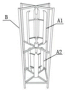
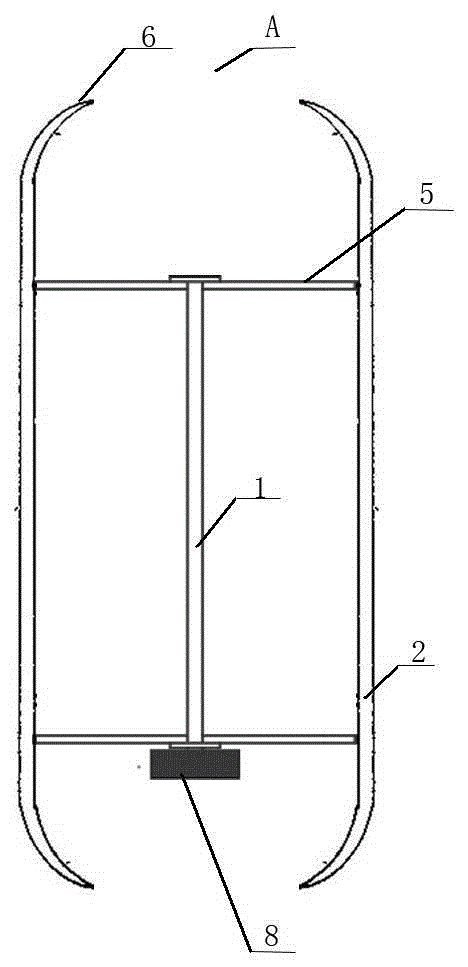
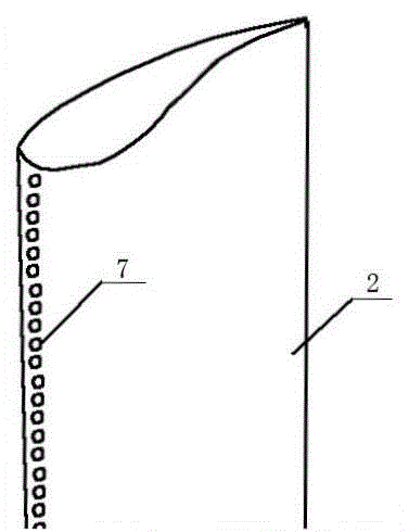
[0026] A double-rotor wind power generating set, comprising a generator 8, an upper wind rotor A1 arranged above the generator, and a lower wind rotor A2 arranged below the generator, and the generator 8, the upper wind rotor and the lower wind rotor are arranged on a cross-shaped frame perpendicular to the ground In B, the upper wind wheel is connected to the casing of the generator, and the lower wind wheel is connected to the intermediate shaft of the generator. The rotation directions of the upper wind wheel and the lower wind wheel are opposite; The vertical shaft 1 of the wind rotor is connected to the shaft of the generator 8, the vertical shaft of the wind rotor is perpendicular to the ground, and three blades 2 are installed on the vertical shaft 1; the blades are wing-shaped blades, and the leading edge a of the blade is provided with a turbulence prom...


PUM


Abstract

The invention relates to a double-rotor wind power generation unit and belongs to the technical field of wind power generation. According to the technical scheme, a power generator (8), an upper wind wheel and a lower wind wheel are arranged in a cross-shaped frame in the mode of being perpendicular to the ground, and the upper wind wheel and the lower wind wheel rotate in opposite directions; each wind wheel (A) is composed of a vertical shaft (1) and blades (2); the vertical shaft (1) of each wind wheel is connected with a shaft of the power generator (8) and is perpendicular to the ground; the corresponding three blades (2) are installed on each vertical shaft (1); the blades are in wing shapes; turbulence promoting components (7) are arranged on the front edges (a) of the blades, cutting is conducted to the rear edges with the 32% positions of the front edges of wing chords (c) of the blades as starting points, and winglets (6) are installed at the upper end and the lower end of each blade of each wind wheel respectively. According to the double-rotor wind power generation unit, when the double-rotor power generator is driven through the upper wind wheel and the lower wind wheel to rotate, the lift force and resistance of wind energy can be used at the same time, reverse rotation is achieved, the rotating speed is increased, and power generation efficiency is improved; the double-rotor wind power generation unit can be started by means of the breeze at the speed of 1m / s, noise is avoided, and the double-rotor wind power generation unit is not directional and is high in wind resistance.

Description

technical field [0001] The invention relates to a double-rotor wind power generating set, in particular to a vertical-axis wind power generating set which starts and generates electricity in a breeze, and belongs to the technical field of wind power generation. Background technique [0002] At present, most of the wind power generators in the background technology adopt a horizontal axis structure, and the direction of the wind rotor is changed through the tail, so that the front of the wind rotor directly rotates against the wind, driving the permanent magnet generator to generate electricity. The existing problems of the background technology are: the noise of the wind wheel is large, the wind resistance is low, the wind speed is high at start-up, and the wind speed needs to be above 2m / s to start, and the power generation efficiency of the generator is low. Contents of the invention [0003] The purpose of the present invention is to provide a double-rotor wind power ge...

Claims


Application Information

Patent Timeline
Patent Type & Authority Applications(China)
IPC IPC(8): F03D9/00F03D3/02F03D3/06
CPCY02E10/74
Inventor 赵欣
Owner TANGSHAN TOYODA TECH
Learn More