Composite-modulation-pulse-code-based 4D imaging photon counting laser radar
A composite modulated pulse and photon counting technology, applied in the re-radiation of electromagnetic waves, the use of re-radiation, measurement devices, etc., can solve the problem of missing target intensity information, achieve accurate identification and judgment, and enrich the effect of target information.
- Summary
- Abstract
- Description
- Claims
- Application Information
AI Technical Summary
Problems solved by technology
Method used
Image
Examples
specific Embodiment approach 1
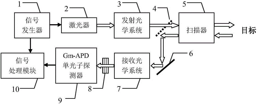
[0024] Specific implementation mode 1: see figure 1 This embodiment is described. A 4D imaging photon counting lidar based on composite modulation pulse coding described in this embodiment includes a signal generator 1, a laser 2, an emission optical system 3, a one-way reflector 4, and a scanner 5 , a total reflection mirror 6, a receiving optical system 7, a narrow-band filter 8, a Gm-APD single-photon detector 9, and a signal processing module 10;
[0025] The composite modulated random pulse signal output end of the signal generator 1 is simultaneously connected with the composite signal input end of the laser 2 and the composite signal input end of the signal processing module 10, and the pulse signal output end of the laser 2 is connected with the pulse signal of the transmitting optical system 3. The signal input end is connected, and the optical signal output by the emission optical system 3 is transmitted through the one-way reflector 4 and then incident on the scanne...
specific Embodiment approach 2
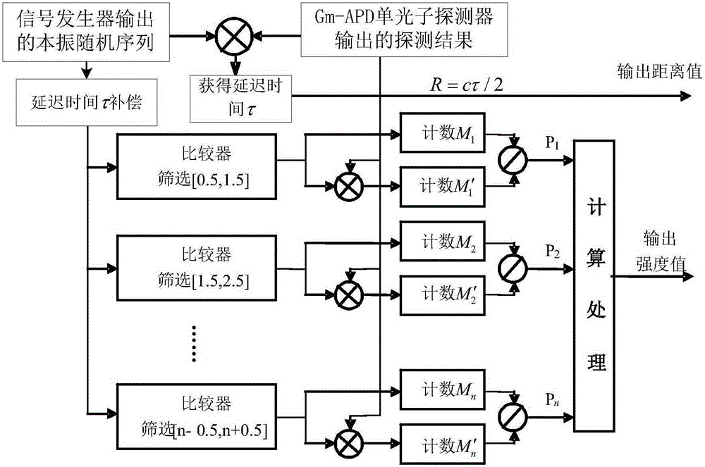
[0026] Specific implementation two: see figure 2 Describing this embodiment, the difference between this embodiment and the 4D imaging photon counting lidar based on composite modulation pulse coding described in Embodiment 1 is that the specific process of the signal processing module 10 processing the received signal is as follows: :
[0027] Step 1: Shift and multiply the detection result output by the Gm-APD single-photon detector 9 and the local oscillator random sequence output by the signal generator 1 to obtain the radar signal delay time τ, through the following formula:
[0028] R=cτ / 2 (Formula 1),
[0029] Obtain the distance value R of the target, wherein the local oscillator random sequence output by the signal generator 1 is a composite modulated random pulse signal, and c represents the speed of light;
[0030] In step 2, delay compensation for the radar signal delay time τ is performed on the local oscillator pulse sequence output by the signal generator 1, ...
specific Embodiment approach 3
[0046] Embodiment 3: The difference between this embodiment and the 4D imaging photon counting lidar based on composite modulation pulse coding described in Embodiment 2 is that each local oscillator encoded pulse signal of the same amplitude described in step 2 is different. M 1 ,M 2 ,…M n The corresponding count result M of each echo pulse signal 1 ′,M 2 ′,…M n The process of obtaining ' is:
[0047] First, multiply the local oscillator encoded pulse signal with the amplitude n and the echo pulse sequence corresponding to the local oscillator encoded pulse signal with the amplitude to obtain the multiplication result,
[0048] Second, count the number of times of multiplication results obtained,
[0049] Finally, each local oscillator encoded pulse signal M with the same amplitude is obtained 1 ,M 2 ,…M n The corresponding count result M of each echo pulse signal 1 ′,M 2 ′,…M n '.
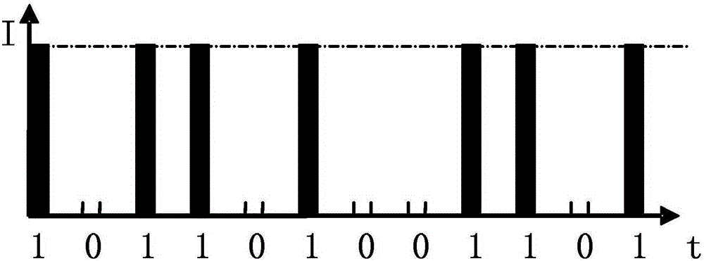
[0050] image 3 is the coding map of the traditional classical pseudo-random co...
PUM
 Abstract
Description
Claims
Application Information
 - R&D
- Intellectual Property
- Life Sciences
- Materials
- Tech Scout
- Unparalleled Data Quality
- Higher Quality Content
- 60% Fewer Hallucinations
Browse by: Latest US Patents, China's latest patents, Technical Efficacy Thesaurus, Application Domain, Technology Topic, Popular Technical Reports.
© 2025 PatSnap. All rights reserved.Legal|Privacy policy|Modern Slavery Act Transparency Statement|Sitemap|About US| Contact US: help@patsnap.com


