Optical fiber cutting device

A cutting equipment and optical fiber technology, applied in the field of optical communication, can solve problems such as low pass rate, inconvenient on-site use, and impact on the quality of on-site splicing, and achieve the effect of ensuring cutting efficiency and cutting accuracy

Active Publication Date: 2015-12-23
SHENZHEN EPLU SCI TECH
View PDF6 Cites 8 Cited by
  • Summary
  • Abstract
  • Description
  • Claims
  • Application Information

AI Technical Summary

Problems solved by technology

[0002] The optical fiber cutters in the related art are expensive and have precise structures, especially the angled optical fiber cutters, which are inconvenient for on-site use
Inexpensive optical fiber cutters are connected by ties, and the quality of the end face of the cut optical fiber is unstable, which affects the quality of on-site splicing, and the qualified rate is low

Method used


Image

  • Optical fiber cutting device
  • Optical fiber cutting device
  • Optical fiber cutting device

Examples


Embodiment Construction

[0044] In order to have a clearer understanding of the technical features, purposes and effects of the present invention, the specific implementation manners of the present invention will now be described in detail with reference to the accompanying drawings.

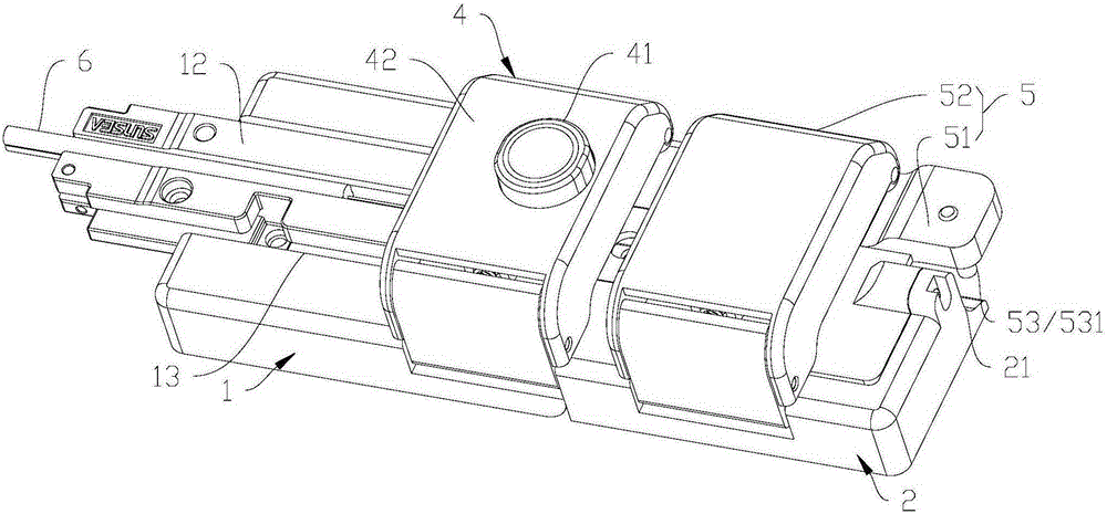
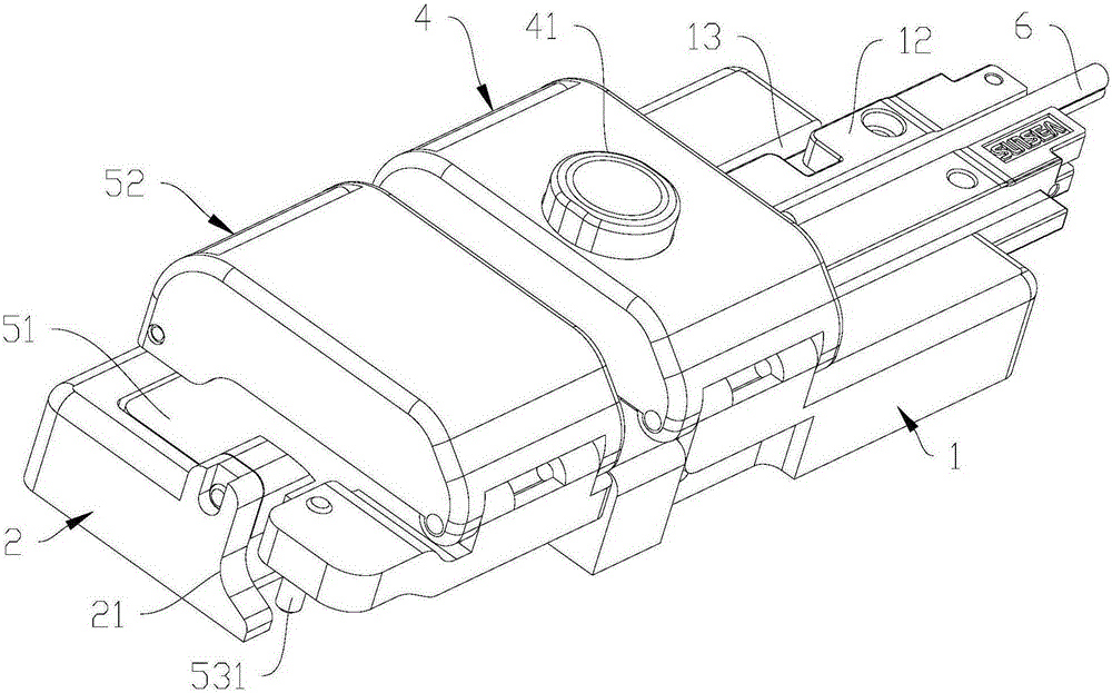
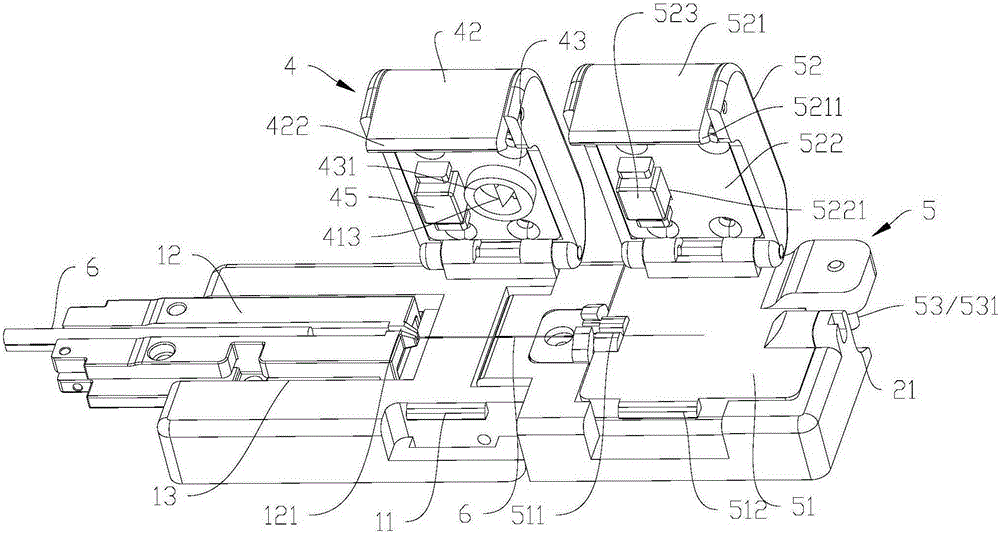
[0045] like Figure 1 to Figure 3 As shown, the optical fiber cutting device in a preferred embodiment of the present invention includes a base 1 , a rotating base 2 , a holding mechanism 3 , a first clamping unit 4 , a cutter assembly 41 and a second clamping unit 5 . One end of the base 1 and one end of the rotating base 2 are hinged to each other, so that the longitudinal ends of the optical fiber 6 to be cut are placed on the base 1 and the rotating base 2 respectively. The holding mechanism 3 is arranged between the base 1 and the rotating base 2 , and provides an active force to keep the rotating base 2 and the base 1 flush. The first clamping unit 4 is arranged on the base 1 to fix the corresponding position of ...


PUM


Abstract

An optical fiber cutting device of the present invention comprises a substrate, a rotating base, a keeping mechanism, a first clamping unit, a cutter assembly and a second clamping unit. One end of the substrate is in hinge joint with one end of the rotating base mutually, and the keeping mechanism is arranged between the substrate and the rotating base to provide an action force for keeping the rotating base and the substrate parallel and level. The first clamping unit is arranged on the substrate and the second clamping unit is arranged on the rotating base to fix the to-be-cut optical fibers at the corresponding positions respectively, the cutter assembly is arranged on the first clamping unit to form shear marks on the to-be-cut optical fibers between the fixed positions of the first and second clamping units, and after the rotating base overturns and breaks the optical fibers, the keeping mechanism enables the rotating base to return automatically, thereby guaranteeing that the rotating base is positioned with the substrate accurately before and after rotation, and guaranteeing the cutting efficiency and the cutting precision.

Description

technical field [0001] The invention relates to the technical field of optical communication, and more specifically, to an optical fiber cutting device. Background technique [0002] The optical fiber cutters in the related art are expensive and have a precise structure, especially the angled optical fiber cutters, which are inconvenient to use on site. Cheap optical fiber cutters are connected by ties, and the quality of the end face of the cut optical fiber is unstable, which affects the quality of on-site splicing, and the qualified rate is low. Contents of the invention [0003] The technical problem to be solved by the present invention is to provide an optical fiber cutting device. [0004] The technical solution adopted by the present invention to solve the technical problem is to construct an optical fiber cutting device, including a base, a rotating seat, a holding mechanism, a first clamping unit, a cutter assembly and a second clamping unit; [0005] One end o...

Claims


Application Information

Patent Timeline
Patent Type & Authority Applications(China)
IPC IPC(8): G02B6/25
CPCG02B6/25
Inventor 黎斌付帅王七月周震
Owner SHENZHEN EPLU SCI TECH
Why Eureka
Try Eureka