Laser device

A laser device and laser beam technology, applied in the laser field, can solve problems such as laser self-excited oscillation and device damage, achieve high output energy, avoid laser self-excited oscillation problems, and have good beam shaping effects

Inactive Publication Date: 2015-12-23
BEIJING GK LASER TECH
View PDF5 Cites 6 Cited by
  • Summary
  • Abstract
  • Description
  • Claims
  • Application Information

AI Technical Summary

Problems solved by technology

[0004] However, the laser beam shaping device serves the laser, and the placement of the beam shaping device will cause the self-excited oscillation of the laser (especially in the transmission of high-energy laser), thus damaging the device

Method used


Image

  • Laser device
  • Laser device

Examples


Embodiment 1

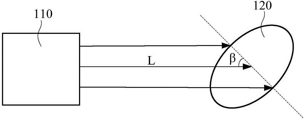
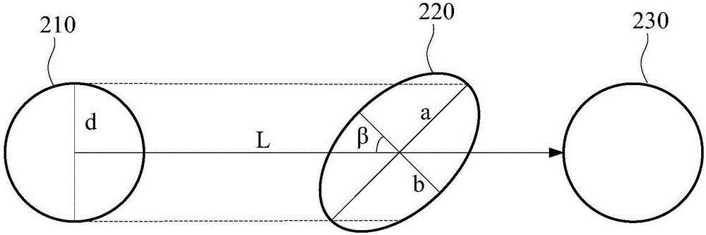
[0015] see figure 1 and figure 2 , figure 1 It is a structural schematic diagram of an embodiment of the laser device in the embodiment of the present invention; figure 2 yes figure 1 Projection plot of the spot in the illustrated embodiment.

[0016] Such as figure 1 As shown, the laser device includes a laser light source 110 and a soft edge diaphragm 120 . The laser device may be a laser (such as a laser amplifier), or other laser light-emitting devices. The laser light source 110 may include a light-emitting device composed of a laser diode array, or other high-power light-emitting devices. The soft-edge diaphragm 120 is elliptical, and is used to homogenize the laser beam emitted by the laser light source 110, and the laser beam L emitted by the laser light source 110 is incident on the soft-edge diaphragm 120 at an incident angle of β, and 0 degree<β <90 degrees.

[0017] Such as figure 2 As shown, the laser light source is used to emit a laser beam L with a ...


PUM


Abstract

The embodiment of the invention discloses a laser device. The laser device comprises a laser light source for shooting out a laser beam with circular light spots, wherein the diameter of the circular light spots is d; and an elliptical soft-edge aperture used for homogenizing the laser beam, wherein the above laser beam shoots into the soft-edge aperture at an incidence angle beta and beta is larger than 0 degree and smaller than 90 degrees. The long axis a of the elliptical soft-edge aperture is larger than or equal to d / cos beta and the short axis b of the elliptical soft-edge aperture is larger than or equal to d*cos beta. According to the technical scheme of the invention, not only all laser spots are homogenized by the soft-edge aperture, but also the laser self-excited oscillation phenomenon caused by the reflection of the soft-edge aperture in the vertical direction can be avoided. Therefore, the beam shaping effect is ensured to be good, and the output energy is ensured to be high at the same time.

Description

technical field [0001] The invention relates to the technical field of lasers, in particular to a laser device. Background technique [0002] Laser shaping technology usually refers to changing the intensity distribution of the incident laser beam to the desired intensity distribution, while adjusting its phase distribution to control its propagation characteristics. The most commonly used laser shaping technology is the laser beam smoothing technology, that is, the intensity of the laser beam is shaped into a uniform distribution. Initially, people used the diaphragm to extract the required light field distribution from the expanded and collimated laser beam. This method of obtaining uniform light intensity distribution by intercepting the diaphragm caused serious energy loss. In 1965, the industry proposed the earliest phase-type beam shaping system without energy loss, which shaped the Gaussian beam into a uniform beam. In the following ten years, due to the limitation ...

Claims


Application Information

Patent Timeline
Patent Type & Authority Applications(China)
IPC IPC(8): G02B27/09
CPCG02B27/0922G02B27/0938
Inventor 张晶张晓雷
Owner BEIJING GK LASER TECH
Why Eureka
Try Eureka