

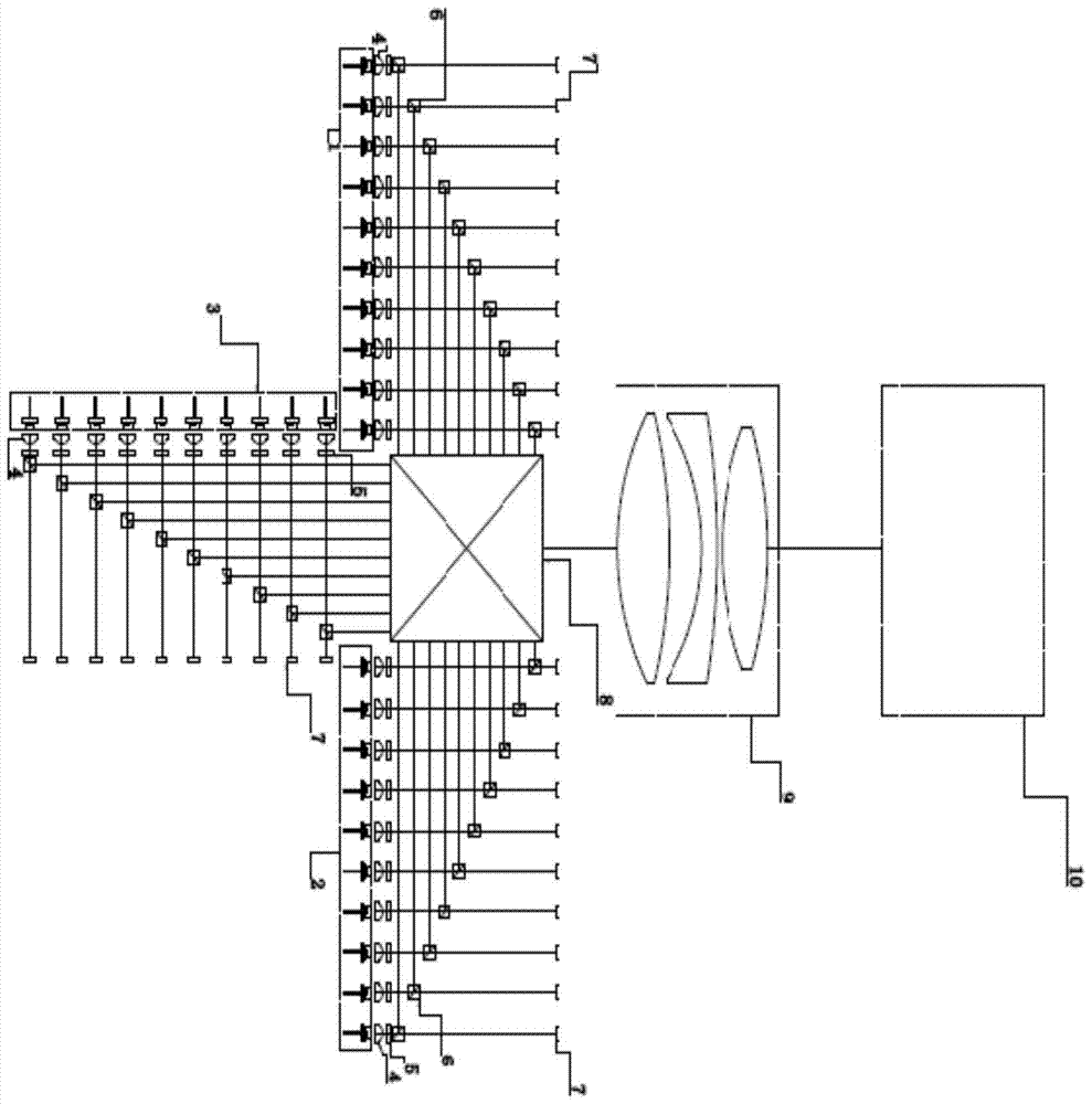
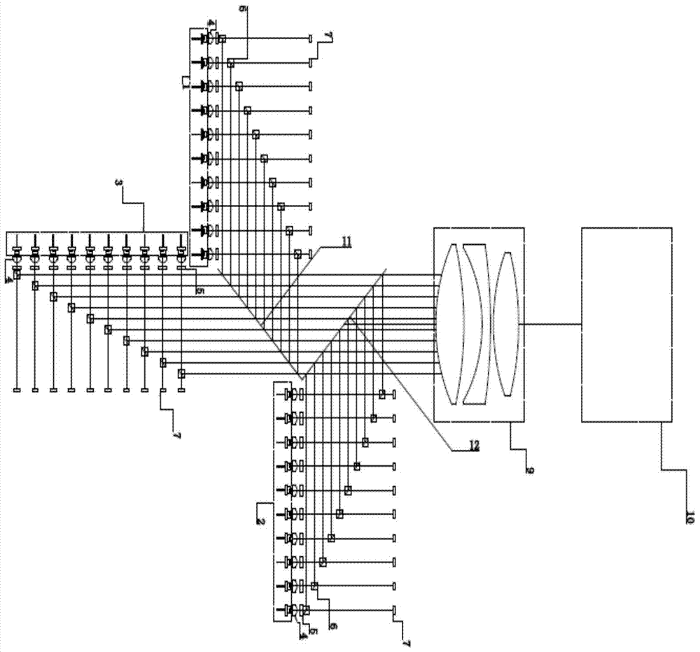
Laser light source for laser projector
A laser projector, laser light source technology, applied in optics, optical components, instruments, etc., can solve the problems of disturbing polarization state and phase, unable to fundamentally eliminate speckle, reduce coherence and other problems, and achieve coherence length reduction, suppression The effect of laser speckle
- Summary
- Abstract
- Description
- Claims
- Application Information
AI Technical Summary
Problems solved by technology
Method used
Image

Examples
Embodiment Construction
[0008] The technical solutions of the present invention will be further described in detail below in conjunction with the accompanying drawings and specific embodiments, so that the advantages and characteristics of the present invention will become clearer along with the description.
[0009] Those skilled in the art can understand that although the following description involves many technical details related to the embodiments of the present invention, this is only an example for illustrating the principle of the present invention, and does not imply any limitation. The present invention can be applied to occasions other than the technical details exemplified below, as long as they do not deviate from the principle and spirit of the present invention.
[0010] In addition, in order to avoid making the description in this manual limited to redundant, in the description in this manual, some technical details that can be obtained in the existing technical documents may be omitt...
PUM
 Abstract
Description
Claims
Application Information