Laser speckle suppression element and suppression method

A laser speckle and suppression element technology, applied in the optical field, can solve the problems of screen deformation, low speckle suppression efficiency, low stability of suppression system, etc., achieve speckle suppression, improve speckle suppression efficiency, and enhance speckle The effect of suppressing the effect

Active Publication Date: 2020-04-24
SHANXI UNIV
View PDF13 Cites 0 Cited by
  • Summary
  • Abstract
  • Description
  • Claims
  • Application Information

AI Technical Summary

Problems solved by technology

The existence of speckle seriously affects the quality of the projected picture, thus affecting the viewing effect. For example, if there is such speckle in the projection screen of the laser movie machine, it will seriously affect the quality of the movie screen
[0003] At present, the commonly used methods of speckle suppression are vibrating screens or rotating scatterers, both of which achieve speckle suppression by superimposing different speckle images over time within the integration time of the human eye. Vibrating screens are used for speckle suppression When using mechanical motors and other driving devices, it will generate noise, deform the screen and shorten its service life, and cause low system stability.
However, when a rotating diffuser (or a rotating optical flat plate) is used for speckle suppression, the stability of the suppression system is low and the speckle suppression efficiency is not high

Method used


Image

  • Laser speckle suppression element and suppression method
  • Laser speckle suppression element and suppression method
  • Laser speckle suppression element and suppression method

Examples


Embodiment Construction

[0037] In some laser speckle suppression methods, speckle suppression is usually achieved by superimposing different speckle images over time within the integration time of the human eye. Perform laser speckle suppression, but noise will be generated during the suppression process, the screen will be deformed and its service life will be shortened, and the system stability will be low; or, a rotating optical flat plate can also be used for speckle suppression, but this suppression method can only achieve The coarse speckle caused by laser interference on the scattering sheet is eliminated, but the fine speckle caused by laser interference on the screen cannot be eliminated. Therefore, the speckle suppression efficiency is not high.

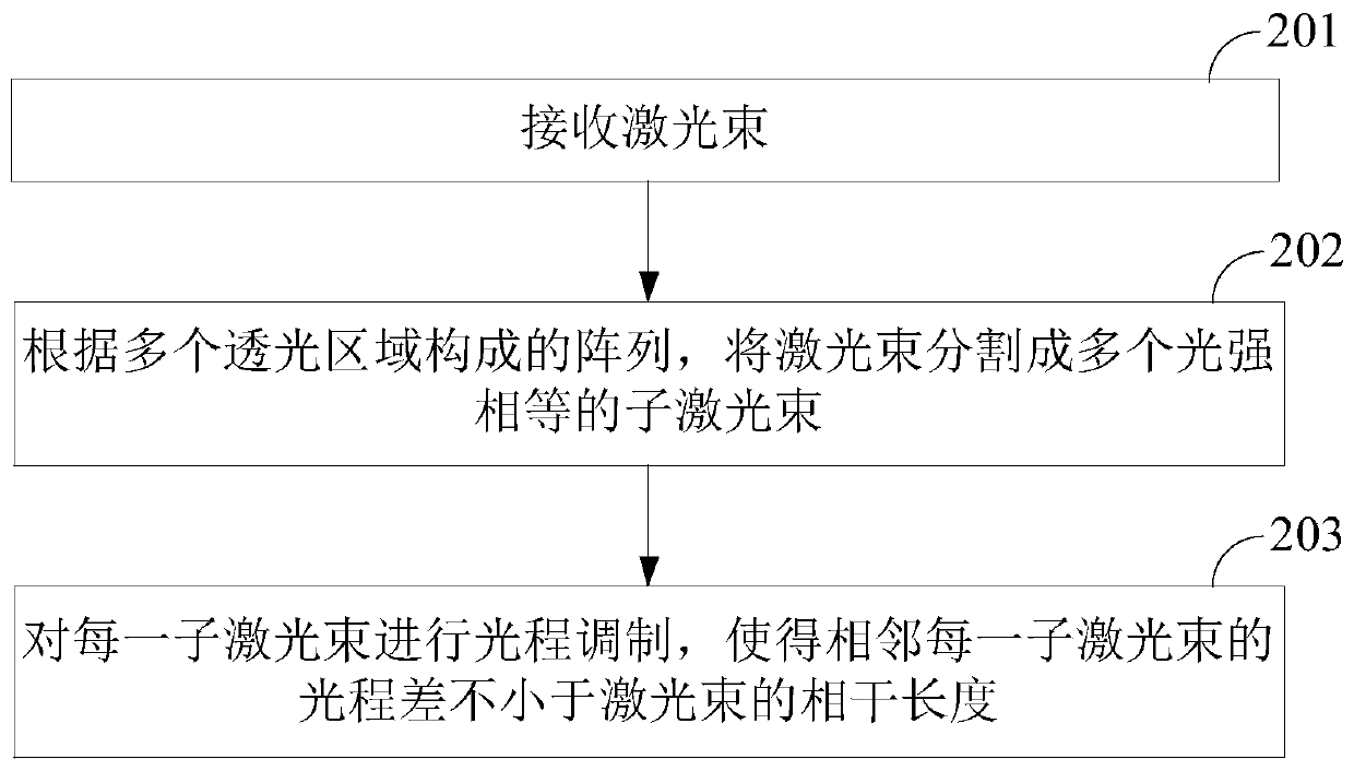
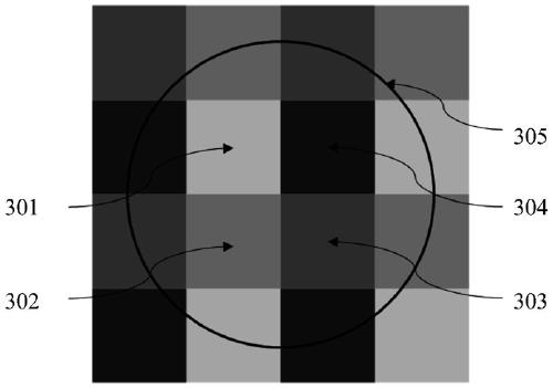
[0038] In order to solve the above-mentioned defects, an embodiment of the present application provides a laser speckle suppression element, which uses a light-transmitting material; includes an array composed of a plurality of light-transmitting r...


PUM

PropertyMeasurementUnit
sizeaaaaaaaaaa
diameteraaaaaaaaaa

Abstract

The invention discloses a laser speckle suppression element and a suppression method, which are used for improving the speckle suppression efficiency and enhancing the speckle suppression effect. Theelement is made of a light-transmitting material and comprises an array formed by a plurality of light-transmitting areas; the transverse size of the light-transmitting area is smaller than the spatial resolution of human eyes; the difference value of the longitudinal sizes of the adjacent light-transmitting areas enables the optical path difference of the laser beams penetrating through the adjacent light-transmitting areas to be not smaller than the coherence length of the laser beams; thus, the time coherence between the adjacent sub laser beams can be destroyed, the spatial coherence of the laser can be destroyed, the adjacent sub laser beams become non-correlated light, spatial superposition of multiple independent speckles can be achieved within the resolution of human eyes, and effective inhibition of the speckles is achieved.

Description

technical field [0001] The invention relates to the field of optical technology, in particular to a laser speckle suppressing element and a suppressing method. Background technique [0002] Due to its advantages of high brightness, pure color and long life, laser light source has gradually replaced xenon light source as the light source of projection system. Due to the strong temporal and spatial coherence of the laser, when the laser is irradiated on the surface of a rough object, it will produce a granular light intensity distribution with bright and dark distribution, which is called speckle. The existence of speckle seriously affects the quality of the projected picture, thereby affecting the viewing effect. For example, if such speckle exists in the projection screen of a laser movie machine, it will seriously affect the quality of the movie screen. [0003] At present, the commonly used methods of speckle suppression are vibrating screens or rotating scatterers, both ...

Claims


Application Information

Patent Timeline
Patent Type & Authority Applications(China)
IPC IPC(8): G02B27/48G03B21/60
CPCG02B27/48G03B21/60
Inventor 仝召民菅泽群
Owner SHANXI UNIV
Why Eureka
Try Eureka