Low-coherence chaotic laser for laser display

A technology of chaotic lasers and laser display, which is applied to devices, optics, instruments, etc. that control the output parameters of lasers, to achieve the effects of small size, easy structure optimization and integration, and simple structure

Pending Publication Date: 2018-10-19
TAIYUAN UNIV OF TECH
View PDF0 Cites 6 Cited by
  • Summary
  • Abstract
  • Description
  • Claims
  • Application Information

AI Technical Summary

Problems solved by technology

[0008] In order to solve the problem of improving the existing laser on the basis of the existing laser chip and providing a miniaturized and

Method used


Image

  • Low-coherence chaotic laser for laser display

Examples


Embodiment Construction

[0016] Specific embodiments of the present invention will be described below in conjunction with the accompanying drawings.

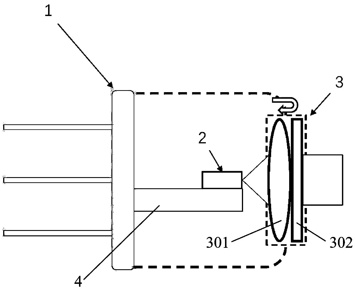
[0017] A low-coherence chaotic laser for laser display, such as figure 1 As shown, it includes a TO package laser housing 1, and there are two to four pins on the outside of the TO package laser housing 1 body, and a laser chip 2 is fixed on the support frame 4 in the TO package laser housing 1, so A cemented lens 3 is fixed at the light exit window of the TO package laser housing 1. The cemented lens 3 is composed of a collimator lens 301 and a transflector 302. The collimator lens 301 and the transflector 302 are sequentially along the optical path. Place and close to fixed, the inner surface of the transflective mirror 302 in contact with the collimator lens 301 is coated with a transflective film; coaxial placement.

[0018] In this embodiment, the model of the TO package laser housing 1 is TO-18, TO-3 or TO-5; the outer surface of the mirror 302 ...


PUM

PropertyMeasurementUnit
Focal lengthaaaaaaaaaa

Abstract

The invention discloses a low-coherence chaotic laser for laser display and relates to the field of light sources for laser display. The laser mainly comprises a TO package laser housing having threepins at the outer side. A laser chip is fixed to a support frame in the TO package laser housing. A cemented lens is fixed to the light-emitting window of the TO package laser housing and is formed bycombining a collimating lens and a transflective lens which are successively placed along an optical path and are fixed in such a way of clinging to each other. The contact inner sides of the collimating lens and the transflective lens are plated with a transflective film. The laser exit center of the laser chip is located at the focal length of the collimating lens. A laser beam is collimated bythe collimating lens and then passes through the transflective lens. The transflective film on the transflective lens transmits a part of the laser beam, and reflects the other part of the laser beamback to the laser chip. Thus, a feedback is provided for the laser chip to form a chaotic laser, thereby reducing the coherence of the laser, achieving speckle suppression, and facilitating the structure optimization and integration of a laser display system.

Description

technical field [0001] The invention relates to the field of lasers used for laser display, in particular to a low-coherence chaotic laser for laser display. Background technique [0002] With its advantages such as large color gamut, high color saturation, high electro-optical conversion efficiency, and long light source life, laser display technology has become the most promising new generation display technology after CRT, plasma, and LCD / LED display technologies. However, due to the extremely high temporal and spatial coherence of laser light, compound speckle exists in laser projection imaging, which seriously reduces the resolution and contrast of projected images. This problem has always been a key issue hindering the development of laser display technology. Therefore, researchers have proposed a variety of methods to suppress speckle by controlling the temporal and spatial coherence of laser light. The specific methods are mainly divided into three categories: [...

Claims


Application Information

Patent Timeline
IPC IPC(8): G02B27/48H01S5/06
CPCH01S5/06G02B27/48
Inventor 赵彤郭园园王安帮高华吴梅
Owner TAIYUAN UNIV OF TECH
Why Eureka
Try Eureka