Fingerprint identification device and fingerprint identification system

A fingerprint recognition and finger technology, applied in the acquisition/organization of fingerprints/palmprints, character and pattern recognition, instruments, etc., can solve the problems of low transmittance and low light energy, and achieve the effect of improving the accuracy.

Active Publication Date: 2015-12-23
BOE TECH GRP CO LTD +1
View PDF5 Cites 78 Cited by
  • Summary
  • Abstract
  • Description
  • Claims
  • Application Information

AI Technical Summary

Problems solved by technology

But because the transmittance of the liquid crystal layer 3 is low, the light energy of the light from the backlight source 1 in the above-mentioned liquid crystal display after passing through the liquid crystal layer 3 twice and reaching the photoelectric sensor 01 is very low, and because the light is diffusely reflected by the finger 6 Back to the photoelectric sensor 01, and the light energy difference of the divergent light diffusely reflected by the valleys and ridges of the fingerprint of the finger 6 is extremely small, and there is also interference of ambient light between the valleys and ridges of the fingerprint, so the above-mentioned liquid crystal display is very difficult. Difficult to accurately identify fingerprints

Method used


Image

  • Fingerprint identification device and fingerprint identification system
  • Fingerprint identification device and fingerprint identification system
  • Fingerprint identification device and fingerprint identification system

Examples


Embodiment 1

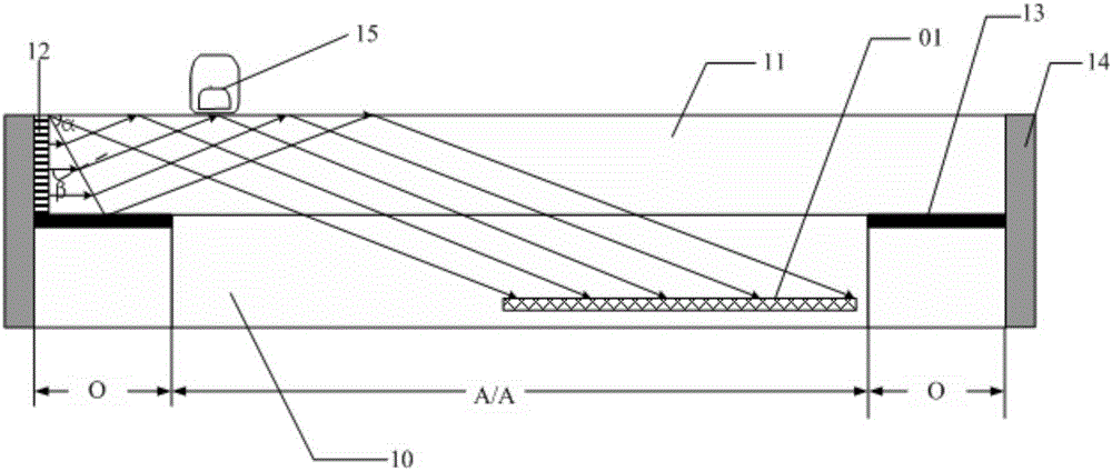
[0071] When the incident angle β is equal to 90°-α, such as Figure 4a As shown, the angle α between the inclined surface of the transparent cover 11 and the upper surface of the transparent cover 11 and the detection area M where the multiple photoelectric sensors 01 are located satisfy the following relationship:

[0072] β=90°-α(1)

[0073] sinβ·n 0 = sin α'·n 1 (2)

[0074] θ 1 =α'+α(3)

[0075] w=h tanθ 1 +h / tanα(4)

[0076] w+d·tanθ 1

[0077] Wherein, α' represents the refraction angle of the parallel light entering the transparent cover 11 , and w represents the coverage area width of the upper surface of the transparent cover 11 irradiated by the parallel light after entering the transparent cover 11 .

[0078] Depend on Figure 4a It can be seen that as long as the light irradiated on the upper surface of the transparent cover plate 11 and the farthest distance from the detection light source 12 is reflected to the layer where the photoelectric senso...

Embodiment 2

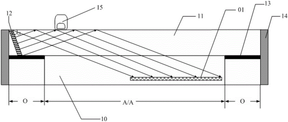
[0080] When the incident angle β is equal to 0°, such as Figure 4b As shown, the angle α between the inclined surface of the transparent cover 11 and the upper surface of the transparent cover 11 and the position of the detection area M where the plurality of photoelectric sensors 01 are located satisfy the following relationship:

[0081] θ 1 =α(6)

[0082] w=h tanθ 1 +h / tanα(4)

[0083] w+d·tanθ 1

[0084] Depend on Figure 4bIt can be seen that as long as the light irradiated on the upper surface of the transparent cover plate 11 and the farthest distance from the detection light source 12 is reflected to the layer where the photoelectric sensor 01 is located, it will not exceed the edge of the display area A / A, that is, the above-mentioned formula (5), so that when the photoelectric sensor 01 is located in the display area A / A, the clamp between the inclined surface of the transparent cover 11 and the upper surface of the transparent cover 11 can be determine...

Embodiment 3

[0115] When the incident angle β is equal to 90°-α, such as Figure 4c As shown, the angle α between the inclined surface of the transparent cover 11 and the upper surface of the transparent cover 11 and the detection area M where the multiple photoelectric sensors 01 are located satisfy the following relationship:

[0116] β=90°-α(1)

[0117] sinβ·n 0 = sin α'·n 1 (2)

[0118] θ 1 =α'+α(3)

[0119] w=h tanθ 1 +h / tanα(4)

[0120] L3=L-w-L2 (9)

[0121] d 1 = L 3 tanθ 1 - - - ( 10 )

[0122] d 2 =d-d 1 (11)

[0123] no 2 sinλ=n 1 ·cosθ 1 (12)

[0124] s = d 2 t a n λ - ...


PUM


Abstract

The invention discloses a fingerprint identification device and a fingerprint identification system. One side of a transparent cover plate is a slope side; a detection light source is arranged on one slope side of the transparent cover plate; when the finger-free control is performed, because the refractive index of the transparent cover plate is greater than the air refractive index, the light which is transmitted to the transparent cover plate from the slope side of the transparent cover plate is fully reflected; and a light intensity is detected by utilizing a photoelectric sensor; when the fingerprint identification device is operated by the finger, the valleys of the fingerprint is not in contact with the transparent cover plate, and the light is fully reflected; the ridges of the fingerprint is in contact with the transparent cover plate; because the refractive index of the transparent cover plate is smaller than the refractive index of the human body, the light is partly refracted and enters into the air and is partly reflected and radiated to the photoelectric sensor, thereby causing the light intensity difference of the reflective light between the valley position and the ridge position is great and thus improving the accuracy of the fingerprint identification device.

Description

technical field [0001] The invention relates to the field of touch technology, in particular to a fingerprint identification device and a fingerprint identification system. Background technique [0002] With the development of fingerprint identification technology, it has been widely used in many fields. Such as mobile phones, tablet computers and TVs in electronic equipment terminals; access control and safes in security protection systems. In the fingerprint identification technology, the fingerprint acquisition methods mainly include optical, capacitive, and ultrasonic imaging methods, among which the fingerprint identification technology that uses optical fingerprint acquisition has a relatively large identification range and relatively low cost. [0003] At present, the optical fingerprint identification technology applied to liquid crystal displays such as mobile phones and other mobile terminals is still immature, such as figure 1 As shown, a liquid crystal display ...

Claims


Application Information

Patent Timeline
Patent Type & Authority Applications(China)
IPC IPC(8): G06K9/00
CPCG06V40/1318G06V40/1324G06V40/1329
Inventor 高健刘英明牛小辰陈小川王海生王倩杨明卢鹏程
Owner BOE TECH GRP CO LTD
Why Eureka
Try Eureka