
A method for displaying live state of substation dynamic equipment based on 3D model

A three-dimensional model, live state technology, applied in the field of electric power, can solve problems such as inability to be intuitive, visual equipment operation and maintenance personnel operation guidance, unable to provide information on the live state of the internal components of the equipment, increase investment in manpower and material resources, etc. Fast, improve on-site installation, save the effect of economical investment

Active Publication Date: 2019-02-19
SHANGHAI MUNICIPAL ELECTRIC POWER CO +1
View PDF9 Cites 0 Cited by
  • Summary
  • Abstract
  • Description
  • Claims
  • Application Information

AI Technical Summary

Problems solved by technology

[0002] Up to now, my country usually adopts on-site inspection and operation methods for physical display of substation dynamic equipment, which shows a large degree of singleness in operation, and equipment maintenance personnel can only find problems at the dynamic equipment site and fix them. To solve the problem, this will increase the investment of manpower and material resources invisibly
On the other hand, for substation dynamic equipment, there are also possible faults that cannot be reproduced. At the same time, considering that the operation mode of the power grid is changeable, different operation modes determine the charged state of the equipment, especially the charged state of the internal components of the equipment. The charged state of the internal parts of the equipment is directly related to the life safety of the maintenance personnel, and the misjudgment of the charged state of the equipment parts is the main cause of casualties in the maintenance work
If the internal components of the power grid equipment are not managed, it is impossible to provide information about the charged status of the internal components of the equipment, and it is impossible to provide operation guidance for equipment operation and maintenance personnel intuitively, visually and intelligently.

Method used


Image

  • A method for displaying live state of substation dynamic equipment based on 3D model

Examples


Embodiment

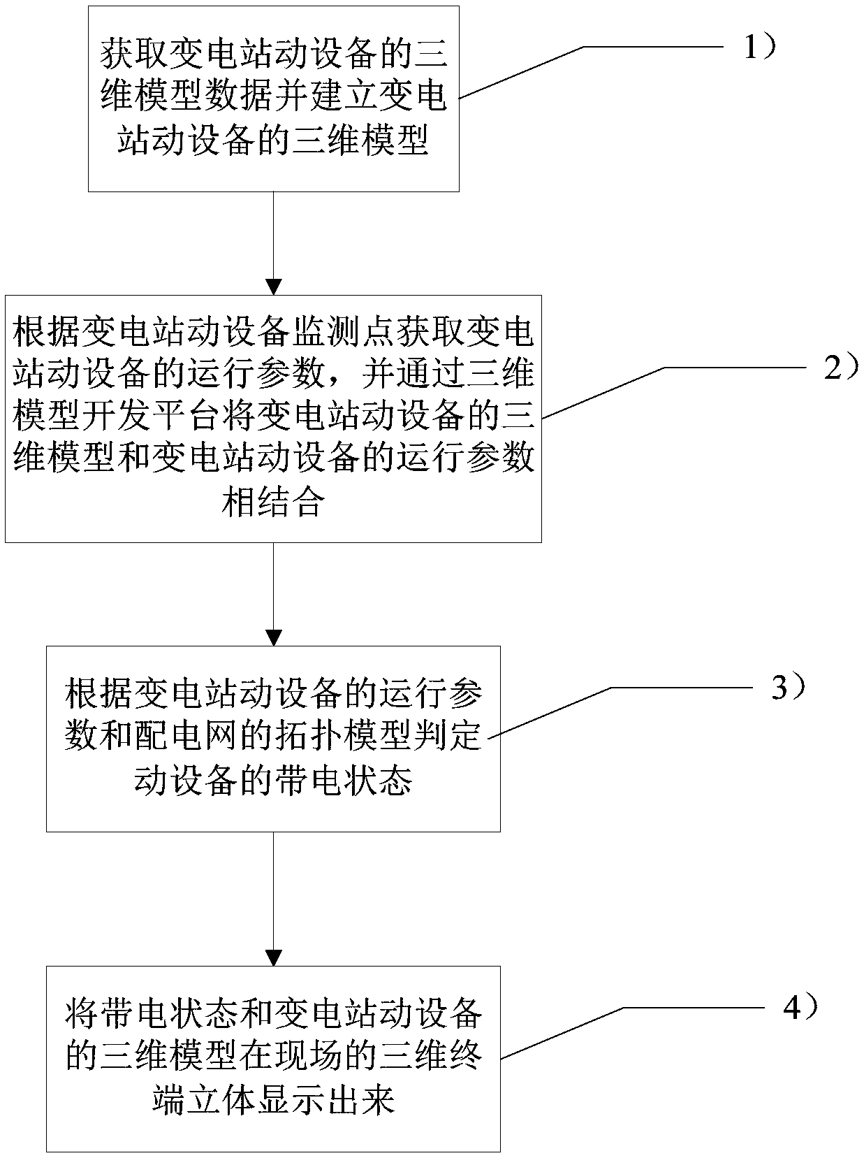
[0024] Such as figure 1 As shown, a three-dimensional model-based method for displaying the live state of substation dynamic equipment includes the following steps:

[0025] 1) Obtain the three-dimensional model data of the substation dynamic equipment and establish the three-dimensional model of the substation dynamic equipment;

[0026] 2) Obtain the operating parameters of the substation dynamic equipment according to the monitoring points of the substation dynamic equipment, and combine the three-dimensional model of the substation dynamic equipment with the operating parameters of the substation dynamic equipment through the three-dimensional model development platform;

[0027] 3) According to the operating parameters of the substation dynamic equipment and the topology model of the distribution network, the live state of the dynamic equipment is determined, which specifically includes the following steps:

[0028] 31) Construct a substation dynamic equipment network mo...


PUM


Abstract

The present invention relates to a transformer substation rotating equipment charged state display method based on a three dimensional model. The method comprises the steps of 1) obtaining the three dimensional model data of the transformer substation rotating equipment and establishing the three dimensional model of the transformer substation rotating equipment; 2) obtaining the operation parameters of the transformer substation rotating equipment according to the transformer substation rotating equipment monitoring points, and combining the three dimensional model of the transformer substation rotating equipment and the operation parameters of the transformer substation rotating equipment via a three dimensional model development platform; 3) determining the charged states of the rotating equipment according to the operation parameters of the transformer substation rotating equipment and a topology model of a power distribution network; 4) displaying the charged states and the three dimensional model of the transformer substation rotating equipment on a on-site three dimensional terminal three-dimensionally. Compared with the prior art, the transformer substation rotating equipment charged state display method based on the three dimensional model of the present invention has the advantages of being good in economic benefit and few in working procedures, being simple, easy, accurate and visual, etc.

Description

technical field [0001] The invention relates to the field of electric power, in particular to a three-dimensional model-based method for displaying the live state of substation dynamic equipment. Background technique [0002] Up to now, my country usually adopts on-site inspection and operation methods for physical display of substation dynamic equipment, which shows a large degree of singleness in operation, and equipment maintenance personnel can only find problems at the dynamic equipment site and fix them. To solve the problem, this will increase the input of manpower and material resources invisibly. On the other hand, for substation dynamic equipment, there are also possible faults that cannot be reproduced. At the same time, considering that the operation mode of the power grid is changeable, different operation modes determine the charged state of the equipment, especially the charged state of the internal components of the equipment. The charged state of the interna...

Claims


Application Information

Patent Timeline
Patent Type & Authority Patents(China)
IPC IPC(8): H02B15/02G06T17/00
Inventor 陈海波郑健王媚袁成谈雪晶陈锦华陈宁林俊王传宝
Owner SHANGHAI MUNICIPAL ELECTRIC POWER CO
Learn More