Phase-locked loop system

A phase-locked loop, the same distance technology, applied in the field of phase-locked loop systems, can solve problems such as low command accuracy and asynchronous clock signals

Inactive Publication Date: 2015-12-23
HEFEI GEYI INTEGRATED CIRCUIT CO LTD +1
View PDF5 Cites 2 Cited by
  • Summary
  • Abstract
  • Description
  • Claims
  • Application Information

AI Technical Summary

Problems solved by technology

[0005] Because the clock signal is transmitted from the above-mentioned phase-locked loop 101, in the transmission path transmitted to the above-mentioned controller 102, command transmission interface 103 and data transmission interface 104, it will be affected by jitter2, therefore, the phase-locked loop 101 sends to the above-mentioned controller 102. The clock signals transmitted by the command transmission interface 103 and the data transmission interface 104 may be out of sync, which in turn makes the accuracy of data and commands transmitted between the SOC and the DRAM chip low

Method used


Image

  • Phase-locked loop system
  • Phase-locked loop system
  • Phase-locked loop system

Examples


Embodiment 1

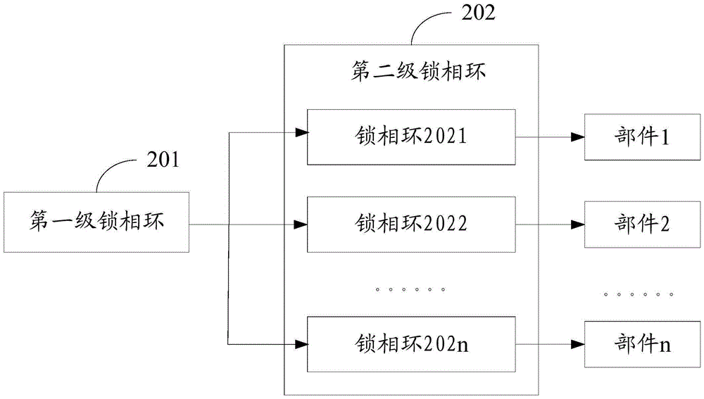
[0021] refer to figure 2 , shows a schematic structural diagram of Embodiment 1 of a phase-locked loop system provided by the present invention, which may specifically include: a first-stage phase-locked loop 201 and a second-stage phase-locked loop 202; wherein, the above-mentioned first-stage phase-locked loop The input terminal of 201 can be connected with the clock;

[0022] The above-mentioned second-stage phase-locked loop 202 may specifically include: a number of phase-locked loops corresponding to the components in the application system; the above-mentioned phase-locked loop may specifically include a feedback loop, and the input end of the above-mentioned phase-locked loop may be connected to the above-mentioned first-stage phase-locked loop The output ends of 201 are closely adjacent, and the output ends of the phase-locked loop may be close to the input ends of the corresponding components.

[0023] The embodiments of the present invention can be applied to elect...

Embodiment 2

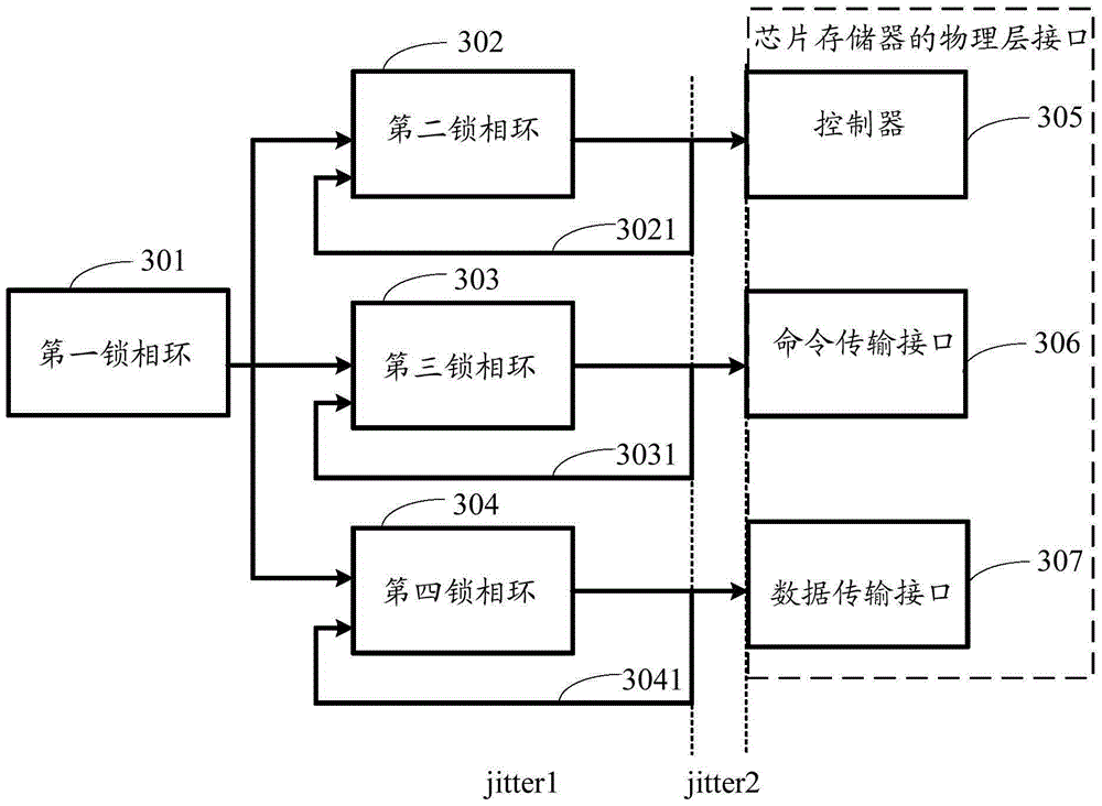
[0034] refer to image 3 , shows a schematic structural diagram of Embodiment 2 of a phase-locked loop system provided by the present invention, which may specifically include: a first phase-locked loop (PLL1) 301, a second phase-locked loop (PLL2) 302, a third phase-locked loop (PLL3) 303, the fourth phase-locked loop (PLL4) 304;

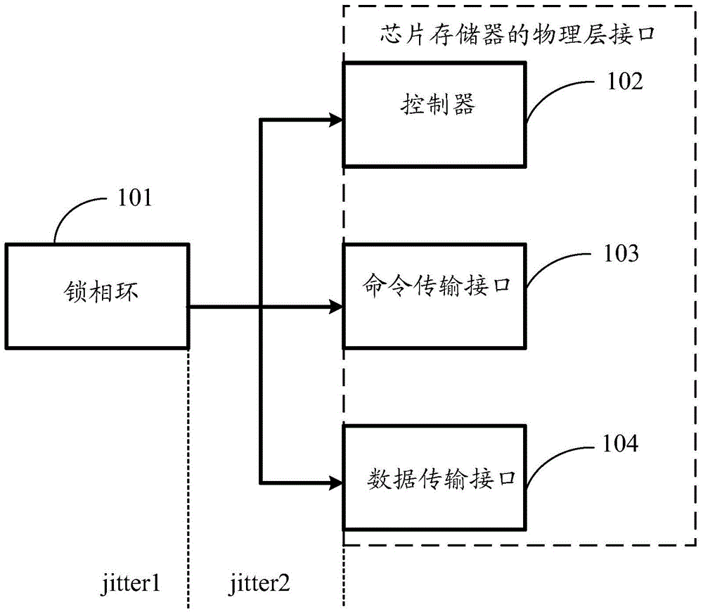
[0035] In the embodiment of the present invention, the application system can be a DDRPHY system, which can specifically include three components: the first component can be a controller (Controller) 305, the second component can be a command transmission interface (CMDPHY) 306, and the third component can be a data Transmission interface (DQPHY) 307;

[0036] In the embodiment of the present invention, the first-stage phase-locked loop may specifically include: a first phase-locked loop 301, and the second-stage phase-locked loop may specifically include: a second phase-locked loop 302, a third phase-locked loop 303, and a fourth phase-locked loo...


PUM


Abstract

Provided in the invention is a phase-locked loop system comprising a first-stage phase-locked loop and a second-stage phase-locked loop. The output terminal of the first-stage phase-locked loop is connected with the input terminal of the second-stage phase-locked loop; and the input terminal of the first-stage phase-locked loop is connected with a clock. The second-stage phase-locked loop contains phase-locked loops with the number corresponding to that of components in an application system; the phase-locked loops include feedback loops; input terminals of the phase-locked loops are adjacent to the output terminal of the first-stage phase-locked loop; and output terminals of the phase-locked loops approach input terminals of the corresponding components. According to the embodiment of the invention, a synchronous rate of clock signals received by all components of the application system and thus accuracy of data and command transmission between electronic devices is improved.

Description

technical field [0001] The invention relates to the field of electronic technology, in particular to a phase-locked loop system. Background technique [0002] PLL (phase locked loop, phase locked loop) is a frequency and phase synchronization technology realized by the principle of feedback control, which can be widely used in various electronic devices, so that the clock output by the circuit of the electronic device is synchronized with the external reference clock , when the frequency or phase of the reference clock changes, the PLL system will detect this change and adjust the output frequency through its internal feedback system until the two are resynchronized. [0003] In the process of transmitting the clock signal to the application system in the electronic device, the phase-locked loop is prone to jitter. The jitter may include: jitter1 brought by the phase-locked loop and the clock transmission path between the phase-locked loop and the above-mentioned application...

Claims


Application Information

Patent Timeline
Patent Type & Authority Applications(China)
IPC IPC(8): H03L7/08
Inventor 胡俊舒清明
Owner HEFEI GEYI INTEGRATED CIRCUIT CO LTD
Why Eureka
Try Eureka