Underwater measurement lifesaving device based on visual analysis

A technology of underwater measurement and life-saving devices, which is applied to closed-circuit television systems, instruments, anti-theft alarms, etc. It can solve the problems that underwater sports personnel cannot conduct direct observation, danger occurs, and cannot alarm in time, so as to shorten the detection of danger. The effect of saving time, improving efficiency, and improving economy

Inactive Publication Date: 2015-12-23
HARBIN ENG UNIV
View PDF4 Cites 4 Cited by
  • Summary
  • Abstract
  • Description
  • Claims
  • Application Information

AI Technical Summary

Problems solved by technology

[0003] The purpose of the present invention is to solve the problems that underwater sports personnel cannot conduct direct observation during their work and cannot timely alarm when danger occurs, and provide an underwater measurement life-saving device based on visual analysis

Method used


Image

  • Underwater measurement lifesaving device based on visual analysis
  • Underwater measurement lifesaving device based on visual analysis
  • Underwater measurement lifesaving device based on visual analysis

Examples


specific Embodiment approach 1

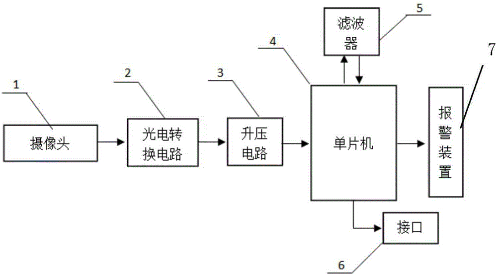
[0043] Specific implementation mode one: the following combination figure 1 This embodiment will be described. This embodiment includes a visual tracking system, a photoelectric conversion circuit, an amplifier circuit, and a single-chip microcomputer.

[0044] The visual tracking system is composed of a single camera, the output end of the camera 1 is connected with the photoelectric conversion circuit 2; the input end of the photoelectric conversion circuit 2 is connected with the camera 1, and the output end is connected with the amplifier circuit 3; the input end of the amplifier circuit 3 is connected with the photoelectric conversion circuit 2, the output end is connected with the single-chip microcomputer 4; the input end of the single-chip microcomputer 4 is connected with the amplifier circuit 3.

[0045] The single-chip microcomputer processes the information sent back by the visual tracking system, and calculates the target's motion position (xc k ,yc k ) for real...

specific Embodiment approach 2

[0061] Specific embodiment two: the difference between this embodiment and embodiment one is that it also includes an alarm device 7, and when the single-chip microcomputer 4 judges that the target is in danger, it transmits a signal to the alarm device 7, and the alarm device 7 issues an alarm.

[0062] The single-chip microcomputer processes the information sent back by the visual tracking system, and calculates the target's motion position (xc k ,yc k ) for real-time recording, analyze the motion characteristics of the target according to the transmitted images, and judge whether the target is in a drowning state. If the target is in a state of drowning, the single-chip microcomputer sends a signal to the alarm device, and the alarm device sends an alarm.

specific Embodiment approach 3

[0063] Specific embodiment three: the difference between this embodiment and embodiment two is that it also includes an interface 6 connected with the man-machine interface and the display system, the input end of the interface 6 is connected with the single-chip microcomputer 4, and the output end is connected with the man-machine operation interface. The interface is connected with the display system.

[0064] In order to allow the operator to observe and process the movement state of the underwater target more intuitively, a man-machine operation interface and a display system are specially added. The purpose of adding the man-machine interface is to artificially intervene in the angle of the camera, and to conduct a comprehensive observation of the underwater environment. The purpose of the display system is to display the underwater environment so that the personnel on the shore can have an intuitive understanding of the underwater environment.


PUM


Abstract

The invention belongs to the field of underwater measurement and lifesaving research, and specifically relates to an underwater measurement lifesaving device based on visual analysis which can measure the underwater motion of people in real time, analyze the underwater behaviors of people and alarm automatically. The underwater measurement lifesaving device comprises a visual tracking system, a photoelectric conversion circuit, an amplifying circuit, a single chip microcomputer, a filter, an interface, an alarm device, and a waterproof shell. Due to the adoption of the visual tracking system, the motion process of a target person can be observed in real time, the underwater motion of the target person can be analyzed intelligently, and an alarm can be given automatically when danger occurs. Therefore, the time for danger finding is shortened, the efficiency of underwater lifesaving is improved, and the economical efficiency is improved.

Description

technical field [0001] The invention belongs to the field of underwater measurement and lifesaving research, and in particular relates to an underwater measurement and lifesaving device based on visual analysis, which can measure people's underwater movement in real time, analyze people's underwater behavior, and can automatically alarm. Background technique [0002] Due to the complex underwater environment, people who are active underwater may encounter unexpected situations, which may cause underwater sports to be unable to proceed normally, or people who are working underwater may be in danger. Traditional underwater lifesaving work relies on lifeguards to find dangers And carry out rescue, which leads to the time of discovering the danger not in time, and sometimes even the danger cannot be found; even if the traditional artificial lifesaving is successful, it is often unknown what causes the danger; and the artificial lifesaving system is highly subjective, Low economy...

Claims


Application Information

Patent Timeline
Patent Type & Authority Applications(China)
IPC IPC(8): H04N7/18G08B13/196
Inventor 王巍张宪亮刘宇恬孙楚琦叶立恒易钰驰孙昕竹陈卫东宋婷韩华韩飞
Owner HARBIN ENG UNIV
Why Eureka
Try Eureka