Lighting device

A technology for lighting devices and lighting units, which is applied to lighting devices, lamp circuit layout, light sources, etc., and can solve problems such as the inability to use high-power LEDs

Inactive Publication Date: 2015-12-23
OSRAM GMBH
View PDF3 Cites 5 Cited by
  • Summary
  • Abstract
  • Description
  • Claims
  • Application Information

AI Technical Summary

Problems solved by technology

Although the step-down converter can provide the step-down function of power factor correction for the LED lighting device, its power factor is affected by the forward voltage

Method used


Image

  • Lighting device
  • Lighting device
  • Lighting device

Examples


Embodiment Construction

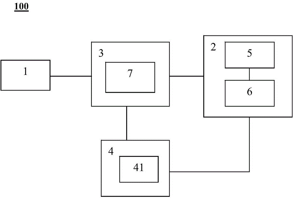
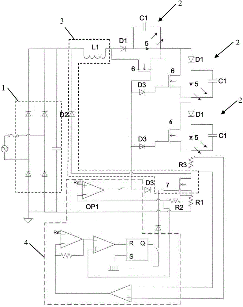
[0022] figure 1 A functional block diagram of the lighting device 100 according to the present invention is shown. The lighting device 100 according to the present invention includes a rectification unit 1 connected to a power supply, a step-down circuit unit 3 connected to the input end of the rectification unit 1, and a lighting unit 2 connected to the step-down circuit unit 3. In addition, the lighting device 100 also includes A main control unit 4 for controlling the step-down circuit unit 3 and the lighting unit 2 respectively, wherein the main control unit 4 also includes a first switch 6 and a second switch for directly controlling the step-down circuit unit 3 and the lighting unit 2 7's sub-controller 41. The light-emitting elements 5 provided in the lighting unit 2 are selectively controlled by the main control unit 4, that is, the main control unit 4 controls the conduction or disconnection of the first switch 6 connected to each light-emitting element 5, so that th...


PUM


Abstract

The invention relates to a lighting device. The lightning device comprises a rectification unit connected with a power supply, at least a lightning unit connected with the rectification unit through a buck circuit unit, and a buck circuit unit connected with the rectification unit and the lighting unit. The lighting device also comprises a main control unit connected with the buck circuit unit and the lighting unit. The main control unit is arranged to control the input current from the rectification unit to flow past a light emitting part of the lighting unit according to change of the input voltage of the rectification unit, and thus a total forward voltage of the light emitting part is adjusted. When the input voltage is more than the total forward voltage, the buck circuit unit lowers the voltage flowing past the lighting unit and thus the lighting device enters a voltage reduction state.

Description

technical field [0001] The invention relates to a lighting device. Background technique [0002] A buck converter, commonly used to drive LEDs, is a simple-to-design and low-cost solution. However, the power factor (PF) of buck converters generally used in off-line applications is low due to the need for an electrolytic capacitor on the input side. As the application of LEDs for high-power lighting devices becomes more and more popular, the improvement of power factor becomes more and more important and attracts attention. [0003] A solution in the prior art uses a two-stage drive structure to improve the power factor of the drive circuit, wherein the first stage of the drive circuit is usually designed as a boost converter for power factor correction (PFC), The step-up converter is also used to provide constant voltage, and the second stage of the driving circuit is designed as a step-down converter to control the current of the LED string. The driving circuit with the ...

Claims


Application Information

Patent Timeline
IPC IPC(8): H05B37/02H05B44/00
CPCH05B45/48H05B45/325H05B45/395H05B45/375H05B45/355
Inventor 胡飏
Owner OSRAM GMBH
Why Eureka
Try Eureka