Component mounting device and method of calibration in component mounting device

A technology of installation device and installation position, which is applied in the direction of electrical components, electrical components, etc., can solve the problems of high cost of component installation devices, poor image recognition, etc., and achieve the effect of reducing the number and cost

Active Publication Date: 2015-12-23
FUJI KK
View PDF7 Cites 4 Cited by
  • Summary
  • Abstract
  • Description
  • Claims
  • Application Information

AI Technical Summary

Problems solved by technology

[0004] In the component mounting device described in Patent Document 1, cameras are provided separately for component recognition and substrate recognition. Therefore, two cameras are provided, so that

Method used


Image

  • Component mounting device and method of calibration in component mounting device
  • Component mounting device and method of calibration in component mounting device
  • Component mounting device and method of calibration in component mounting device

Examples


Embodiment Construction

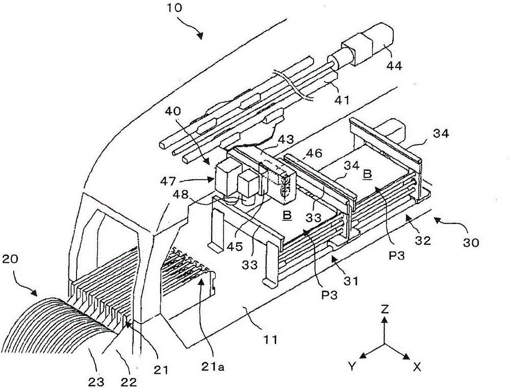
[0036] Embodiments of the present invention will be described below based on the drawings. like figure 1 As shown, the component mounting apparatus 10 includes a component supply unit 20 , a board transport unit 30 , and a component transfer unit 40 .

[0037]The components supply part 20 is comprised by the structure which arrange|positioned the some tape feeder 21 in parallel along the X-axis direction on the base 11 as an example. The tape feeder 21 is detachably attached to the main body frame 22 detachably attached to the base 11, and has a supply tape reel 23 which is wound and accommodated in a row at intervals. A strip of multiple electronic components. Although not shown in the figure, a motor serving as a driving source for pitch feeding the tape is built in the inside of the tape feeder 21, and the tape is fed out one pitch at a time by this motor, and the electronic components accommodated in the tape are sequentially supplied. It reaches the component supply po...


PUM


Abstract

The objective of the present invention is to capture a fiducial marker provided at a base side and a fiducial marker provided at a mounting head side with one recognition camera. In the present invention, a substrate recognition optical path (81) for recognizing a substrate marker (BM) provided on a substrate (B) from above and a component recognition optical path (82) for recognizing a component picked up by a pickup nozzle (55) from below are separately provided for the optical axis of the recognition camera (50), a first fiducial marker (91) to be captured via the substrate recognition optical path is disposed at a predetermined position on the base side, a second fiducial marker (93) to be captured via the component recognition optical path is disposed at a predetermined position on the mounting head (47) side, and a calculation means is provided for calculating the positional relationship of the first and second fiducial markers relative to the optical axis of the recognition camera by capturing the first fiducial marker and the second fiducial marker with the recognition camera.

Description

technical field [0001] The present invention relates to a component mounting device for mounting components on a substrate and a calibration method for the component mounting device, and more particularly to a component mounting device and a calibration method in which a single recognition camera can be used for component recognition and substrate recognition. Background technique [0002] In the component mounting apparatus, a mounting head and a substrate recognition camera are mounted on a movable table movable in X-axis and Y-axis directions relative to a base, and a component recognition camera is fixed on the base. Then, the board mark provided on the board positioned at the mounting position by the board transfer device is recognized by the board recognition camera, and the movement amount of the moving table is corrected based on the position of the board mark. In addition, during the process of moving the component adsorbed by the suction nozzle from the component s...

Claims


Application Information

Patent Timeline
IPC IPC(8): H05K13/04H05K13/08
CPCH05K13/0812H05K13/0818H05K13/089
Inventor 伊藤秀俊水野贵幸川合英俊田中启太
Owner FUJI KK
Why Eureka
Try Eureka