Integrated reversing joint device applied to robots

A robot and joint technology, applied in the field of integrated reversing joint devices, can solve the problems of inconvenient control of the mechanical arm, high assembly cost and design cost, and achieve the effect of improving the appearance, simple structure and enhanced stability

Active Publication Date: 2017-04-12
郑枭林
View PDF7 Cites 0 Cited by
  • Summary
  • Abstract
  • Description
  • Claims
  • Application Information

AI Technical Summary

Problems solved by technology

[0004] The purpose of the present invention is to provide an integrated reversing joint device applied to a robot, which mainly solves the problems of inconvenient control of the mechanical arm, high assembly cost and high design cost of the existing robot.

Method used


Image

  • Integrated reversing joint device applied to robots
  • Integrated reversing joint device applied to robots
  • Integrated reversing joint device applied to robots

Examples


Embodiment

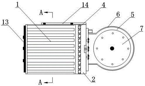
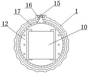
[0031] Such as Figure 1~5 As shown, the present invention provides a new robot joint reversing control device, which includes a housing 1, a bearing 2, an external joint 5, a brush base module, a crank load tray 7, a first gear motor 10 and a driving device.

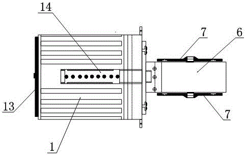
[0032] The first reduction motor 10 is connected with the crank load tray 7 through the transmission shaft 8, and is used for controlling the rotation of the crank load tray 7 in the X direction. The outer joint 5 is located outside the casing 1, and the outer joint has gears for transmitting reversing power inside, and a protective cover 6 is also arranged outside the outer joint. At the same time, the outer joint 5 is provided with a drive shaft hole in the Y direction, and the drive shaft 8 passes through the drive shaft hole, and then connects to the crank load tray 7 .

[0033] The driving device is used to control the outer joint and the crank load tray 7 to rotate in the Y direction at the same time. Specificall...


PUM


Abstract

The invention discloses an integrated steering knuckle device applied in a robot. The integrated steering knuckle device applied in the robot comprises a shell, an outer connector, a bearing, a brushing piece base module, a crank load tray, a first gear motor and a driving device, wherein the first gear motor is connected with the crank load tray by a transmission shaft so as to be used for controlling the crank load tray to rotate in the X direction; the bearing is in sliding connection with the shell; one end of the bearing is connected with a placing groove positioned in the shell; the first gear motor and the driving device are clamped in the placing groove; the driving device is connected with the shell so as to be used for controlling the outer connector and the crank load tray to rotate in the Y direction simultaneously by the bearing; and the brushing piece base module is connected with the first gear motor and the driving device simultaneously so as to be used for enabling outside current to be introduced, and driving the first gear motor and the driving device to work. The integrated steering knuckle device disclosed by the invention can be used for effectively solving problems that a mechanical arm is inconvenient to control, high in assembling cost and lines are wound in an existing robot, so that integrated steering control on knuckle parts of the robot is realized.

Description

technical field [0001] The invention relates to a robot joint control device, in particular to an integrated reversing joint device applied to a robot. Background technique [0002] At present, among the components of most robots, the most important thing is the design of its joints, which is the key part to control the flexible movement of the robot. The so-called robot joint is the part that realizes the bending of the curved rod or the free direction of the mechanical arm. For example, it needs to realize the two-way rotation power to make the robot completely simulate the human arm movement. [0003] In the existing robots, the joint part is generally designed with a joint steering gear. This joint steering gear is essentially the same as the deceleration single motor, and has only one direction of power. Row. It can be seen that for the control of the existing robot manipulator, not only the procedure is relatively complicated, but also the assembly cost is relatively...

Claims


Application Information

Patent Timeline
Patent Type & Authority Patents(China)
IPC IPC(8): B25J17/00B25J9/12
Inventor 郑枭林
Owner 郑枭林
Why Eureka
Try Eureka