Loader static pressure transmission control system

A technology of transmission control and loader, which is applied in the direction of transmission control, mechanical equipment, components with teeth, etc., can solve the problems of low production efficiency, high labor intensity, easy flameout, etc., and achieve improved control safety and maintenance Convenient and convenient stepless speed regulation effect

Inactive Publication Date: 2014-06-04
龙工(上海)机械制造有限公司
View PDF7 Cites 2 Cited by
  • Summary
  • Abstract
  • Description
  • Claims
  • Application Information

AI Technical Summary

Problems solved by technology

[0008] The technical problem to be solved by the present invention is to provide a loader hydrostatic transmission control system that is easy to operate, safe and reliable, easy to install and maintain, high in operation safety, energy-saving and consumption-reducing, and solves the cumbersome operation of the current transmission and control methods , the labor intensity is high, and the driver’s technical requirements are high; the relative positional relationship between the transmission components is strict, and the overall layout is more restricted; Load changes and impacts caused by environmental changes are almost transmitted to the engine, which can easily cause drastic changes in speed, and it is easy to stall when overloaded, resulting in high fuel consumption and fast wear of the engine; low transmission efficiency, resulting in large energy loss and high fuel consumption; Poor reliability of electronic control system, high failure rate and low production efficiency

Method used


Image

  • Loader static pressure transmission control system
  • Loader static pressure transmission control system
  • Loader static pressure transmission control system

Examples


Embodiment Construction

[0026] In order to make the present invention more comprehensible, preferred embodiments are described in detail below with accompanying drawings.

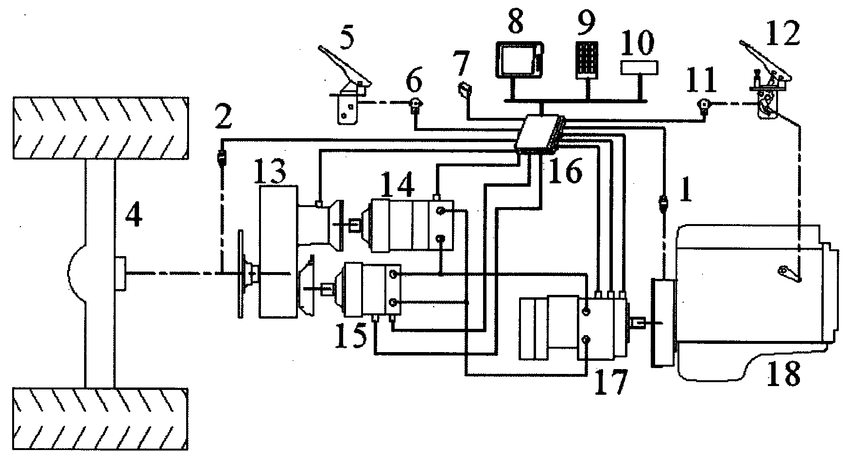
[0027] The present invention is a loader hydrostatic transmission control system, such as image 3 As shown, it includes a controller 16, the controller 16 is respectively connected with the transmission shaft speed sensor 2, the brake pedal displacement sensor 6, the direction switch 7, the display 8, the operation panel 9, the diagnosis port 10, the accelerator pedal displacement sensor 11, the engine speed Sensor 1, travel pump 17, first motor 14, second motor 15, gearbox 13 are connected, travel pump 17 is connected with engine 18, one end of gearbox 13 is connected with bridge 4, and the other end of gearbox 13 is connected with first motor 14. The second motor 15 is connected. The transmission shaft speed sensor 2 is connected with the output shaft of the gearbox 13, the brake pedal displacement sensor 6 is connected with t...


PUM


Abstract

The invention discloses a loader static pressure transmission control system which comprises a controller. The controller is respectively connected with a transmission shaft rotation speed sensor, a brake pedal displacement sensor, a direction switch, a display, an operating panel, a diagnosing opening, an accelerator pedal displacement sensor, an engine rotation speed sensor, a travelling pump, a first motor, a second motor and a gearbox. The traveling pump is connected with an engine. One end of the gearbox is connected with a bridge. The other end of the gearbox is connected with the first motor and the second motor. The loader static pressure transmission control system has the advantages that the loader static pressure transmission control system is convenient to operate and control, safe and reliable, stable and soft in vehicle speed change and convenient to mount and maintain, transmission system efficiency can be increased greatly, full-automatic stepless speed change is achieved, reasonable engine power output distribution and utilization by vehicles are achieved, fuel consumption is lowered, energy is saved, multiple vehicle operation parameters can be checked on instruments, multiple misoperation simulating and safety prompting functions are provided by the system, and operation safety is increased.

Description

technical field [0001] The invention relates to a static pressure transmission control system of a loader, which belongs to the technical field of loaders. Background technique [0002] At present, the mainstream loaders on the market generally use hydraulic transmission, and the power of the engine is transmitted to the gearbox through the torque converter, and the gearbox drives the front and rear axles. The engine drives the pump wheel of the torque converter, and the power is transmitted to the turbine wheel of the torque converter through the working oil in the torque converter housing. Due to the joint action of the pump wheel, the turbine wheel and the guide wheel in between, the torque converter can operate within a certain range. The output speed and torque are automatically adjusted according to the size of the load. This type of equipment generally does not need an electronic control system, and the switching of driving gears depends on the self-adjustment of the ...

Claims


Application Information

Patent Timeline
IPC IPC(8): F16H61/02F16H61/40F16H61/26
CPCF16H61/0206F16H61/421F16H61/431F16H2061/1208
Inventor 龚润弘胡传荣李萍王孙濂
Owner 龙工(上海)机械制造有限公司
Why Eureka
Try Eureka