
Centrifugal type mechanical speed limiter

A speed limiter, centrifugal technology, applied in the field of centrifugal mechanical speed limiter, can solve problems such as failure and limited configuration, and achieve the effect of increasing fatigue resistance, prolonging service life and saving materials

Active Publication Date: 2015-12-30
BEIJING INST OF SPACECRAFT SYST ENG +1
View PDF4 Cites 9 Cited by
  • Summary
  • Abstract
  • Description
  • Claims
  • Application Information

AI Technical Summary

Problems solved by technology

When the rotary kinematic pair is used, in order to avoid the shaft being stuck or the rotation is not flexible, which will affect its speed limiting function and performance, the cleanliness of the rotating shaft is relatively high; since the spring of the traction weight is usually a tension spring, The requirements for spring failure prevention are also high, so the adaptability of the existing mechanical overspeed governor to the environment can be further improved, and there is a certain risk of failure
For different working environments and usage requirements, the available configurations are limited

Method used


Image

  • Centrifugal type mechanical speed limiter
  • Centrifugal type mechanical speed limiter
  • Centrifugal type mechanical speed limiter

Examples


Embodiment Construction

[0027] Below in conjunction with description of drawings and specific embodiments, the present invention will be further described:

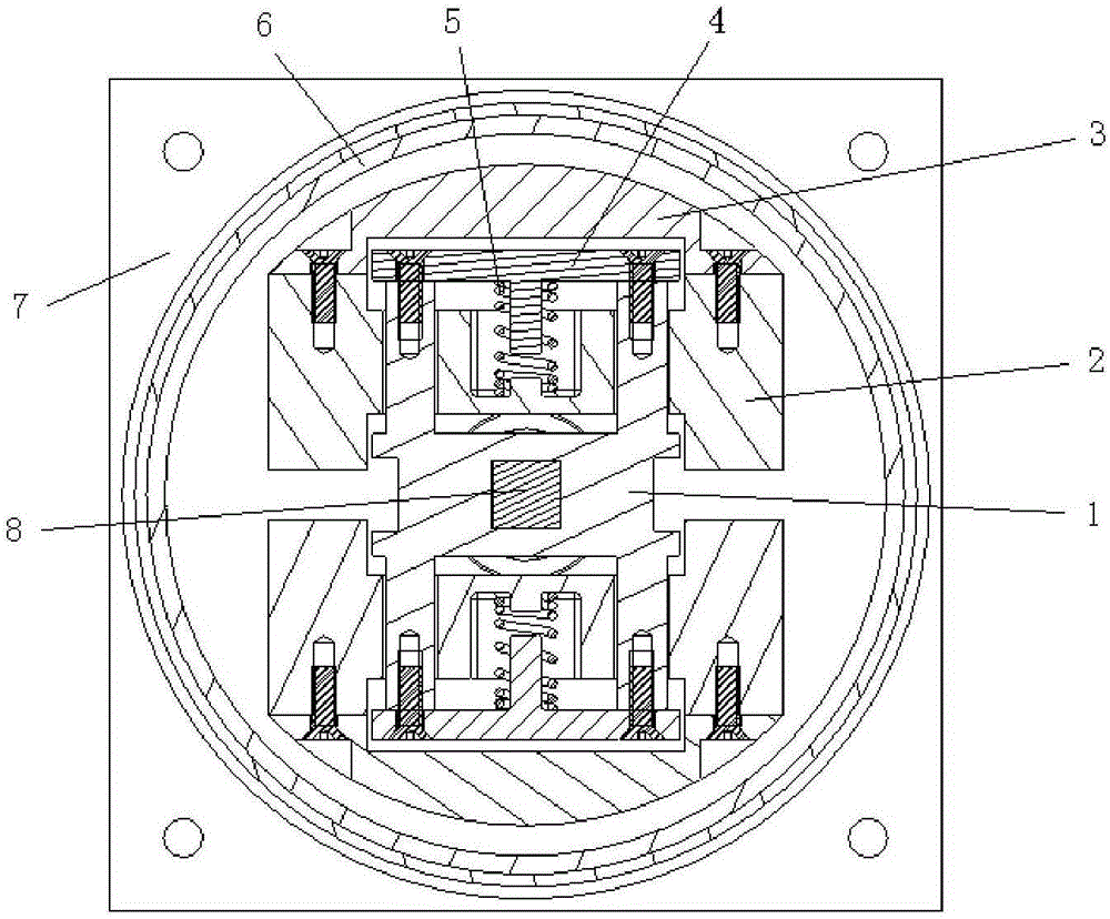
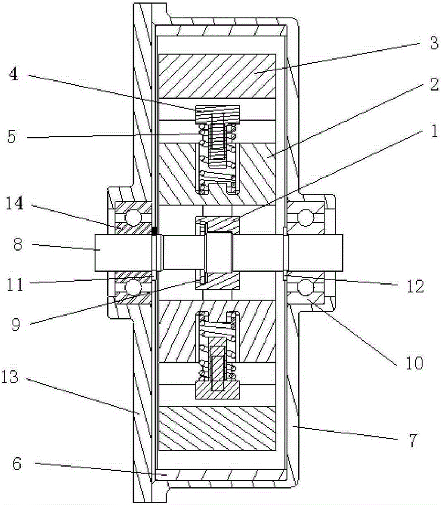
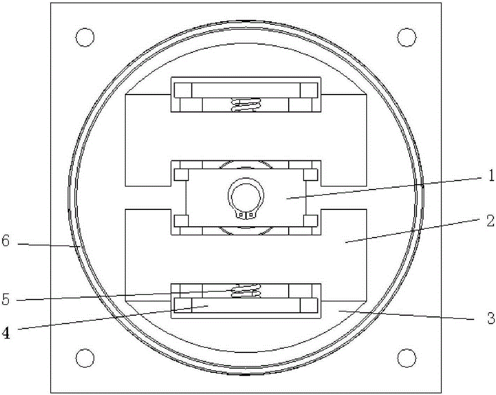
[0028] Such as figure 2 As shown, a centrifugal mechanical speed limiter includes a support frame 1, a counterweight 2, a friction block 3, a baffle 4, a spring 5, a brake hub 6, a casing 7, a rotating shaft 8, a bearing 10 and a mounting plate 13. The two ends of the rotating shaft 8 are respectively installed on the housing 7 and the mounting plate 13 through the bearings 10, the supporting frame 1 is installed on the rotating shaft 8, the two ends of the supporting frame 1 are provided with guide rails, and the two baffles 4 are respectively installed on the supporting frame 1 On the end faces of the guide rails at both ends, the two counterweights 2 are respectively set on the guide rails at both ends of the support frame 1, and the spring 5 is installed at the vertical guiding position in the middle of the baffle 4, and pressed between the...


PUM


Abstract

The invention discloses a centrifugal type mechanical speed limiter, which is suitable for speed limit mechanisms of elevators and stretchable mechanisms and the like, and comprises a support frame, balancing weights, fiction blocks, baffle plates, a spring, a brake hub, a shell, a rotating shaft, a bearing and a mounting plate, wherein the two ends of the rotating shaft are respectively arranged on the shell and the mounting plate through the bearing, the support frame is arranged on the rotating shaft, guide rails are arranged on the two ends of the support frame, the two baffle plates are respectively arranged on the end surfaces of the guide rails which are arranged on the two ends of the support frame, the two balancing weights are respectively sleeved on the guide rails which are arranged on the two ends of the support frame, the spring is arranged on a vertical guiding position of the middle of the baffle plates, and is compressed between the baffle plates and the balancing weights, the fiction blocks and the balancing weights are connected, the brake hub is sleeved in the shell and is fixedly connected with the shell, and the shell and the mounting plate are fixedly connected. The rotating shaft and the support frame rotate and drive the balancing weights and the fiction blocks, and the fiction blocks and the brake hub are contacted and produce tangential friction force, thereby producing rotating brake force to the rotating shaft. The centrifugal type mechanical speed limiter is simple in structure, small in volume and high in reliability.

Description

technical field [0001] The invention relates to a centrifugal mechanical speed governor, which belongs to the technical field of mechanical speed governors. Background technique [0002] The mechanical speed limiter usually uses the centrifugal force generated by the rotating motion to realize the deceleration or braking of the moving object. The mechanical speed limiter can be applied to the deceleration and braking of mining vehicles, elevators and other devices, and can also be applied to the deployment speed control of telescopic deployment mechanisms. The speed limiter of the elevator is relatively widely used at present. The principle is that when the elevator falls rapidly, the shaft of the speed limiter connected to it rotates rapidly. When the speed reaches a certain value, the weight inside the speed limiter moves away from the shaft under the action of centrifugal force. The heart moves and triggers the alarm device to realize the braking function. [0003] The ...

Claims


Application Information

Patent Timeline
Patent Type & Authority Applications(China)
IPC IPC(8): B66B5/04
Inventor 郭一竹史文华李潇
Owner BEIJING INST OF SPACECRAFT SYST ENG
Learn More