Flow enlarging valve and hydraulic steering system

A flow amplification and throttle valve technology, applied in the direction of fluid steering mechanism, fluid pressure actuating device, servo motor assembly, etc., can solve the problems of large hydraulic energy loss, large hydraulic energy loss and large hydraulic shock of flow amplification valve, etc. Achieve the effect of reducing energy loss, saving energy and reducing fuel consumption

Active Publication Date: 2015-12-30
GUANGXI LIUGONG MASCH CO LTD
View PDF11 Cites 25 Cited by
  • Summary
  • Abstract
  • Description
  • Claims
  • Application Information

AI Technical Summary

Problems solved by technology

[0003] The technical problem to be solved by the present invention is to provide a flow amplifying valve with small hydraulic energy loss, good controllability and small hydraulic shock in view of the shortcomings of existing flow amplifying valves, such as large hydraulic energy loss, poor controllability, and large hydraulic shock and the steering hydraulic system with the flow amplifying valve
In the present invention, when the flow amplifying valve is in the left or right position, the high-pressure hydraulic oil acting on the L port at the left end or the R port at the right end of the reversing valve merges into the A port or the B port, acting on the hydraulic cylinder, At the same time, the reversing valve also has a load feedback signal port LS port, which can be used as the signal input of the load-sensitive variable pump, so as to solve the problems of large hydraulic energy loss, poor controllability and large hydraulic shock caused by the loader turning.

Method used


Image

  • Flow enlarging valve and hydraulic steering system
  • Flow enlarging valve and hydraulic steering system

Examples


Embodiment Construction

[0020] The specific implementation will be described below in conjunction with the accompanying drawings.

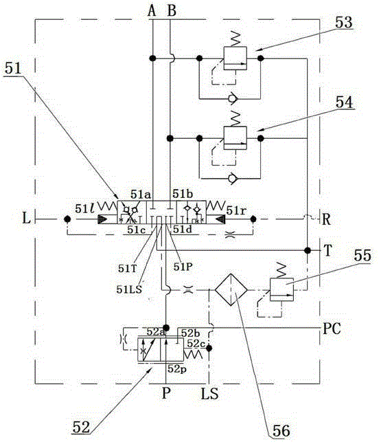
[0021] Such as figure 1 As shown, the flow amplifying valve in this embodiment is provided with P oil port, T oil port, A oil port, B oil port, L oil port, R oil port, LS oil port, PC oil port and PC oil port connected to the reversing valve. Port, which includes a reversing valve 51, a two-position three-way valve 52, a left oil supply valve 53, a right oil supply valve 54, an overflow valve 55, a filter 56, and the oil inlet of the two-position three-way valve 52 It is connected with the P oil port, one oil outlet 52a of the two-position three-way valve is connected with the oil inlet port of the reversing valve, and the other oil outlet 52b of the two-position three-way valve 52 is connected with the PC oil port, and the two-position three-way The spring control chamber 52c of the valve 52 communicates with the LS oil port, and the control chamber on the other side o...


PUM


Abstract

The invention relates to a flow enlarging valve so as to overcome the defects that an existing flow enlarging valve is large in energy loss, poor in controllability and large in hydraulic impact. The flow enlarging valve is provided with an oil port P, an oil port T, an oil port A, an oil port B, an oil port L and an oil port R, wherein the oil port P and the oil port T are connected with an oil inlet and an oil return opening of a reversing valve, the oil port A and the oil port B are correspondingly connected with working oil ports of the reversing valve, and the oil port L and the oil port R are connected with the left hydraulic control end and the right hydraulic control end of the reversing valve. When the reversing valve is in a left position, the oil port L, the oil port P, the oil port A and an oil port LS are communicated with one another, and the oil port B is communicated with the oil port T. When the reversing valve is in a right position, the oil port R, the oil port P, the oil port B and the oil port LS are communicated with one another, and the oil port A is communicated with the oil port T. When the reversing valve is in a middle position, the oil port LS is communicated with the oil port T. According to the flow enlarging valve, high-pressure oil is guided to be converged to the oil port A or the oil port B first to act on a hydraulic oil cylinder, the oil port LS is used as the signal input of a load-sensitive variable pump, and the problems of being large in hydraulic energy loss, poor in controllability and large in hydraulic impact caused in the steering process of a loading machine can be solved through the principle.

Description

technical field [0001] The invention relates to a hydraulic control component, more specifically, to a flow amplifying valve and a steering hydraulic system with the flow amplifying valve. Background technique [0002] At present, the steering hydraulic system of domestic loaders is generally a quantitative system. Compared with the variable system, the quantitative system has the advantages of high maturity, good reliability, strong anti-pollution ability, and high cost performance. However, the displacement of the quantitative system is not variable. , In the process of steering, the excess flow inevitably has throttling loss and overflow loss, which makes the loader have disadvantages such as serious energy consumption, poor controllability, and large hydraulic shock. At present, among the more commonly used steering schemes for domestic loaders, the steering scheme with a small displacement steering gear and a flow amplifying valve is adopted. The loss on the priority va...

Claims


Application Information

Patent Timeline
Patent Type & Authority Applications(China)
IPC IPC(8): F15B13/02F15B13/16B62D5/08
Inventor 姜炜初长祥梁振国谭艳辉范武德农棉庚
Owner GUANGXI LIUGONG MASCH CO LTD
Why Eureka
Try Eureka