Magnetically-driven valve device

A magnetic drive and valve device technology, applied in valve devices, valve operation/release devices, sliding valves, etc., can solve problems such as difficult to achieve full sealing, and achieve rapid opening and closing, reliable external sealing effect

Active Publication Date: 2015-12-30
CHENGDU TAIHUA ZHONGCHENG TECH GRP CO LTD
View PDF5 Cites 5 Cited by
  • Summary
  • Abstract
  • Description
  • Claims
  • Application Information

AI Technical Summary

Problems solved by technology

[0004] The purpose of the present invention is to provide a magnetically driven valve-like device, which solves the problem that existing valves are difficult to achieve full sealing

Method used


Image

  • Magnetically-driven valve device
  • Magnetically-driven valve device
  • Magnetically-driven valve device

Examples


Embodiment 1

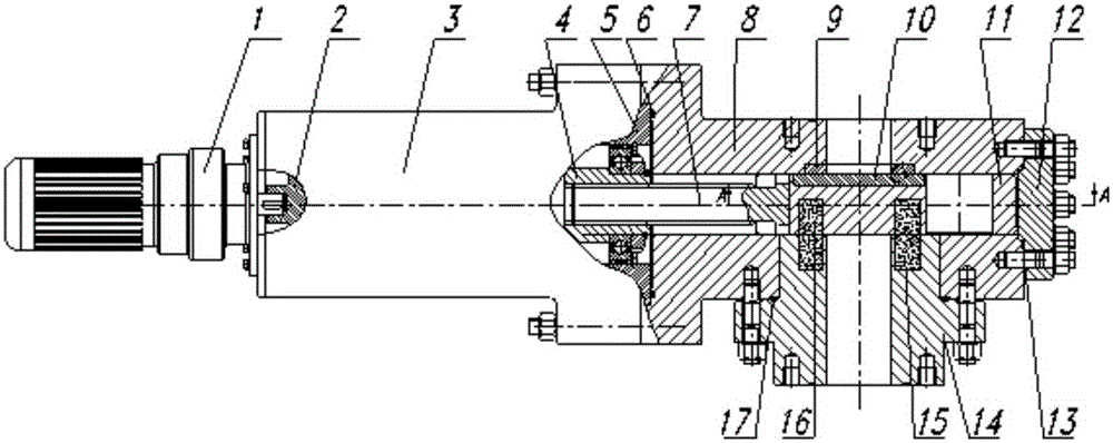
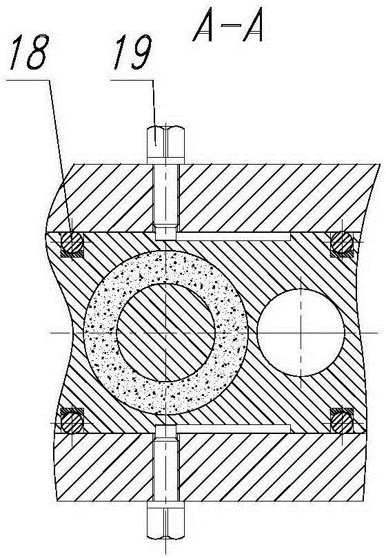
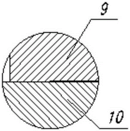
[0041] The magnetic pair of the magnetically driven valve-like device provided in this embodiment is mutual attraction, and the specific structure of the device is as follows: figure 1 As shown, it includes: motor reducer 1, outer rotor 2, actuator bracket 3, inner rotor 4, actuator spacer 5, valve body seal ring 6, transmission shaft 7, valve body 8, static seal body 9, dynamic seal Body 10, flashboard 11, valve body flange 12, valve body flange sealing ring 13, magnetic force flange 14, static magnet 15, moving magnet 16, magnetic force flange sealing ring 17, ball 18, limit pin 19.

[0042] The motor reducer 1 is fixed on the transmission bracket 3, the outer rotor 2 is connected by a shaft hole, and the shaft of the motor reducer 1 is connected to the outer rotor 2 by a key;

[0043] The valve body 8 is an integral structure, and the inner wall side consistent with the medium channel is fixedly installed with a static sealing body 9;

[0044] The valve body 8 and the exte...

Embodiment 2

[0059] The acting force of the magnetic pair of the magnetically driven valve-like device provided in this embodiment is mutual attraction, and its specific structure is as follows: Figure 6 As shown, it includes: motor reducer 1, outer rotor 2, transmission bracket 3, inner rotor 4, spacer 5, valve body sealing ring 6, transmission shaft 7, static sealing body 9, dynamic sealing body 10, gate 11 , valve body flange 12, valve body flange seal ring 13, static magnet 15, moving magnet 16, magnetic force flange seal ring 17, ball 18, limit pin 19, sealed magnetic force flange 14, connected by flange Valve body 8.

[0060] The static magnet 15 and the moving magnet 16 constitute the magnetic pair of mutual attraction force;

[0061] Both the static magnet 15 and the static sealing body 9 are installed on the inner end face of the sealed magnetic flange 14;

[0062] Both the moving magnet 16 and the moving sealing body 10 are installed on the side corresponding to the gate plate...

Embodiment 3

[0067] The acting force of the magnetic pair of the magnetically driven valve-like device provided in this embodiment is a repulsive force, and its specific structure is as follows: Figure 7 As shown, it includes: transmission bracket 3, inner rotor 4 connected by thread, spacer 5, valve body sealing ring 6, transmission shaft 7, static sealing body 9, dynamic sealing body 10, gate plate 11, valve body flange 12. Valve body flange sealing ring 13, static magnet 15, moving magnet 16, magnetic flange sealing ring 17, ball 18, limit pin 19, hand wheel 20, outer rotor 2 connected with the hand wheel 20 using a shaft The valve body 8 connected by welding and the magnetic force flange 14 connected by welding are adopted.

[0068] The transmission bracket 3, the inner rotor 4 and the outer rotor 2 constitute the main structure of the transmission;

[0069] One side of the medium channel of the valve body 8 is provided with an integrally processed medium channel connection pipe, whi...


PUM


Abstract

The invention discloses a magnetically-driven valve device. The magnetically-driven valve device comprises a power source, driver and a valve body which are connected in sequence, wherein a valve body flange is fixed to the other end of the valve body in a sealed mode, a drive shaft and a gate plate which are connected movably are arranged in a channel of the valve body, the drive shaft is connected with the driver, a magnetic flange penetrates through the side wall of the valve body to be arranged, a through medium channel penetrating through the magnetic flange, the gate plate and the valve body is radially formed, and the power source drives the driver to drive the gate plate to move in the channel of the valve body. The magnetically-driven valve device adopts a magnetic pair made of a high-temperature-resisting permanent-magnet material to provide the acting force required by valve sealing without a backpressure condition and adopts a high-temperature-resisting high-pressure corrosion and radiation resistance sealing pair to achieve planar and linear-contact rigid sealing of a valve. Reliable outer sealing can be achieved by adopting connection modes including the driver, static sealing structures of sealing rings and flanges, welding and the like. Smooth passing of a fluid and a large-particle medium can be achieved by adopting the full-sized medium channel.

Description

technical field [0001] The invention belongs to the technical field of valves, and in particular relates to a magnetically driven valve-like device. Background technique [0002] The nuclear power and petrochemical fields have very high requirements for the internal and external sealing of valves working under high temperature, high pressure, strong corrosive, strong leakage medium and strong radioactive working conditions, but they are subject to conditions such as sealing materials, sealing structures, radioactivity and force. It is difficult to realize the full sealing of the valve, especially in the medium of extremely small molecules such as helium, and the inner sealing is difficult to meet the requirements. [0003] At the same time, for the material conveying pipeline system, in addition to the strict requirements on the internal and external sealing of the valve, the problem of the smooth passage of larger particle size materials such as high-temperature gas-cooled ...

Claims


Application Information

Patent Timeline
Patent Type & Authority Applications(China)
IPC IPC(8): F16K3/02F16K31/11F16K31/04
CPCF16K3/02F16K31/04F16K31/0668F16K31/10
Inventor 赵克中
Owner CHENGDU TAIHUA ZHONGCHENG TECH GRP CO LTD
Why Eureka
Try Eureka