Magnetically actuated valve mechanism
A valve device, magnetic drive technology, applied in the direction of valve device, sliding valve, valve operation/release device, etc., can solve the problem of difficult to achieve full sealing, and achieve the effect of rapid opening and closing and reliable external sealing
- Summary
- Abstract
- Description
- Claims
- Application Information
AI Technical Summary
Problems solved by technology
Method used
Image
Examples
Embodiment 1
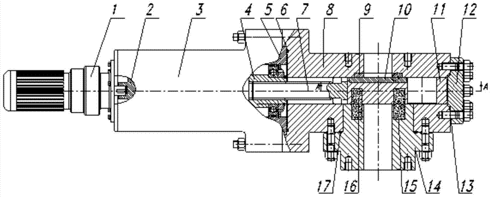
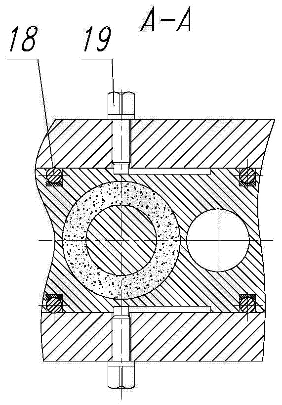
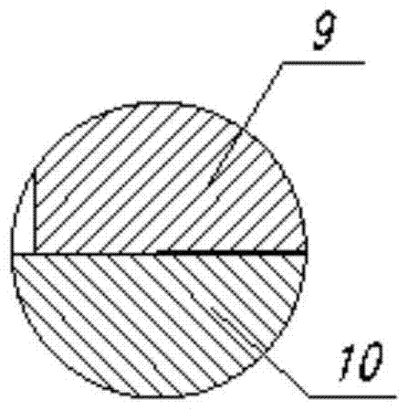
[0041] The magnetic pair of the magnetically driven valve device provided in this embodiment is a mutual attraction, and the specific structure of the device is as follows: figure 1 As shown, it includes: motor reducer 1, outer rotor 2, actuator bracket 3, inner rotor 4, actuator spacer 5, valve body seal ring 6, transmission shaft 7, valve body 8, static seal body 9, dynamic seal Body 10, flashboard 11, valve body flange 12, valve body flange sealing ring 13, magnetic force flange 14, static magnet 15, moving magnet 16, magnetic force flange sealing ring 17, ball 18, limit pin 19.
[0042] The motor reducer 1 is fixed on the transmission bracket 3, the outer rotor 2 is connected by a shaft hole, and the shaft of the motor reducer 1 is connected to the outer rotor 2 by a key;
[0043] The valve body 8 is an integral structure, and the inner wall side consistent with the medium channel is fixedly installed with a static sealing body 9;
[0044] The valve body 8 and the externa...
Embodiment 2
[0059] The acting force of the magnetic pair of the magnetically driven valve device provided in this embodiment is a mutual attraction, and its specific structure is as follows: Image 6 As shown, it includes: motor reducer 1, outer rotor 2, transmission bracket 3, inner rotor 4, spacer 5, valve body sealing ring 6, transmission shaft 7, static sealing body 9, dynamic sealing body 10, gate 11 , valve body flange 12, valve body flange seal ring 13, static magnet 15, moving magnet 16, magnetic force flange seal ring 17, ball 18, limit pin 19, sealed magnetic force flange 14, connected by flange Valve body 8.
[0060] The static magnet 15 and the moving magnet 16 constitute the magnetic pair of mutual attraction force;
[0061] Both the static magnet 15 and the static sealing body 9 are installed on the inner end face of the sealed magnetic flange 14;
[0062] Both the moving magnet 16 and the moving sealing body 10 are installed on the side corresponding to the gate plate 11 ...
Embodiment 3
[0067] The acting force of the magnetic pair of the magnetically driven valve device provided in this embodiment is a repulsive force, and its specific structure is as follows: Figure 7 As shown, it includes: transmission bracket 3, inner rotor 4 connected by thread, spacer 5, valve body sealing ring 6, transmission shaft 7, static sealing body 9, dynamic sealing body 10, gate plate 11, valve body flange 12. Valve body flange sealing ring 13, static magnet 15, moving magnet 16, magnetic flange sealing ring 17, ball 18, limit pin 19, hand wheel 20, outer rotor 2 connected with the hand wheel 20 using a shaft The valve body 8 connected by welding and the magnetic force flange 14 connected by welding are adopted.
[0068] The transmission bracket 3, the inner rotor 4 and the outer rotor 2 constitute the main structure of the transmission;
[0069] One side of the medium channel of the valve body 8 is provided with an integrally processed medium channel connection pipe, which is...
PUM
 Abstract
Description
Claims
Application Information
 - R&D
- Intellectual Property
- Life Sciences
- Materials
- Tech Scout
- Unparalleled Data Quality
- Higher Quality Content
- 60% Fewer Hallucinations
Browse by: Latest US Patents, China's latest patents, Technical Efficacy Thesaurus, Application Domain, Technology Topic, Popular Technical Reports.
© 2025 PatSnap. All rights reserved.Legal|Privacy policy|Modern Slavery Act Transparency Statement|Sitemap|About US| Contact US: help@patsnap.com


