Air injection enthalpy increasing system, air conditioning unit with the system and the enthalpy increasing control method

A technology of air injection to increase enthalpy and control methods, which is applied in the direction of irreversible cycle compressors, refrigerators, compressors, etc., and can solve problems such as reverse leakage of solenoid valves, backflow of refrigerant back to the flash evaporator, and impact on the stability of the heat pump system. , to achieve the effect of preventing refrigerant backflow and improving stability

Active Publication Date: 2018-02-16
GREE ELECTRIC APPLIANCES INC
View PDF7 Cites 0 Cited by
  • Summary
  • Abstract
  • Description
  • Claims
  • Application Information

AI Technical Summary

Problems solved by technology

However, it still has the following disadvantages: due to the delay of the temperature sensing package and the requirements of the sampling time interval, it will inevitably happen that the enthalpy injection solenoid valve is not closed in time, which will cause the refrigerant at the enthalpy injection port of the compressor to flow back into the flash evaporator At the same time, the commonly used solenoid valve still has reverse leakage when it is closed, so that it will seriously reduce the performance of the heat pump system and affect the operation stability of the heat pump system
[0004] Therefore, due to the existence of refrigerant backflow in the above-mentioned existing system, which seriously reduces the performance of the heat pump system and affects the operation stability of the heat pump system, the present invention researches and designs a new air injection enthalpy increasing system, an air conditioning unit with the system and The enthalpy control method

Method used


Image

  • Air injection enthalpy increasing system, air conditioning unit with the system and the enthalpy increasing control method
  • Air injection enthalpy increasing system, air conditioning unit with the system and the enthalpy increasing control method

Examples


Embodiment Construction

[0031] The specific implementation manners of the present invention will be further described in detail below in conjunction with the accompanying drawings and embodiments. The following examples are used to illustrate the present invention, but are not intended to limit the protection scope of the present invention.

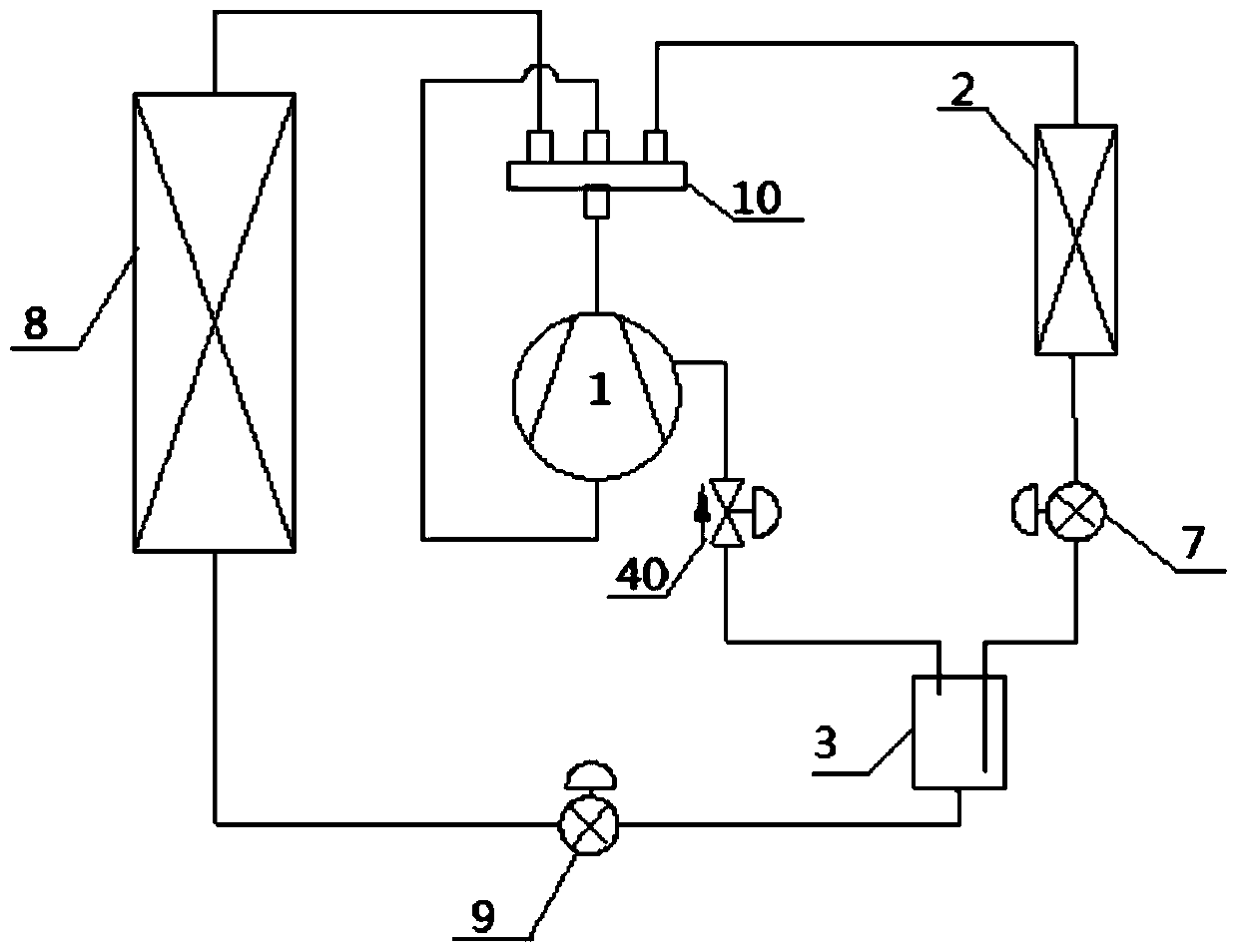
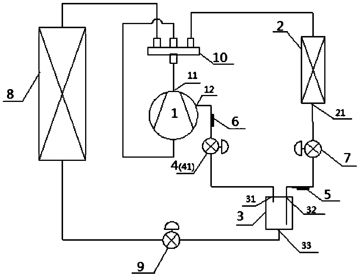
[0032] Such as figure 2 As shown, a gas injection enthalpy increasing system provided by the present invention includes a compressor 1, a condenser 2 connected to the compressor outlet 11, and a flash evaporator 3 connected to the condenser outlet 21, the The flasher 3 also includes a first outlet 31, which is connected to the secondary inlet 12 of the compressor, and at least one The first expansion valve 4. Preferably, the expansion valve 4 is an enthalpy injection expansion valve. According to the gas injection enthalpy increasing system of the present invention, the electromagnetic valve arranged between the first outlet 31 of the flasher and the seconda...


PUM


Abstract

The invention provides a gas injection enthalpy increasing system, comprising a compressor (1), a condenser (2) connected to the compressor outlet (11), and a flash evaporator connected to the condenser outlet (21) (3), the flasher (3) also includes a first outlet (31), the first outlet (31) is connected to the secondary inlet (12) of the compressor, the secondary inlet (12) and At least one first expansion valve (4) is also arranged between the first outlets (31) of the flash evaporator. According to the gas injection enthalpy increasing system of the present invention, it can effectively prevent the refrigerant from flowing back, and improve the efficiency of the air conditioning unit, especially the heat pump. The stability of the system will not affect the normal and stable operation of the air conditioning unit, especially the heat pump system. It can also effectively increase the increment of its enthalpy value on the basis of the original system, and effectively increase the internal energy of the system and its ability to do volume work with the outside. and value. The invention also provides an air conditioning unit with the system and the enthalpy increase control method.

Description

technical field [0001] The invention belongs to the technical field of refrigeration and air conditioning, and in particular relates to an air injection enthalpy increasing system, an enthalpy injection control method of a compressor with an enthalpy injection function, and an air conditioner unit with an air injection enthalpy increasing system. Background technique [0002] In order to increase the effective enthalpy of the unit system, the existing conventional air-conditioning units often add a flash evaporator in the middle pipeline of the refrigeration cycle to evaporate part of the refrigerant and then fill it into the compressor, thereby reducing the refrigerating power in the compressor. The agent plays the role of replenishing qi and increasing enthalpy. However, when the pressure at the inlet of the compressor is higher than the pressure at the outlet of the flash evaporator, part of the refrigerant will flow backwards and flow back into the flash evaporator, seri...

Claims


Application Information

Patent Timeline
Patent Type & Authority Patents(China)
IPC IPC(8): F25B1/06F25B41/04F25B41/06F25B49/02F25B41/20F25B41/34
Inventor 黄玉优吴永和
Owner GREE ELECTRIC APPLIANCES INC
Why Eureka
Try Eureka