Output frequency detection method of resonant mode vibrating gyro

A technology of vibrating gyroscope and detection method is applied in the field of inertia to achieve the effects of reducing coupling, simple analysis and improving detection accuracy

Active Publication Date: 2015-12-30
CHINA UNIV OF MINING & TECH (BEIJING)
View PDF5 Cites 17 Cited by
  • Summary
  • Abstract
  • Description
  • Claims
  • Application Information

AI Technical Summary

Problems solved by technology

Generally, the reference frequency threshold of the oscillating signal is lower, and the longer the calculation interval, the more accurate it is, which requires a trade-off between the bandwidth and the fundamental frequency, which will inevitably limit the driving frequency of the resonant vibrating gyroscope.

Method used


Image

  • Output frequency detection method of resonant mode vibrating gyro
  • Output frequency detection method of resonant mode vibrating gyro
  • Output frequency detection method of resonant mode vibrating gyro

Examples


Embodiment Construction

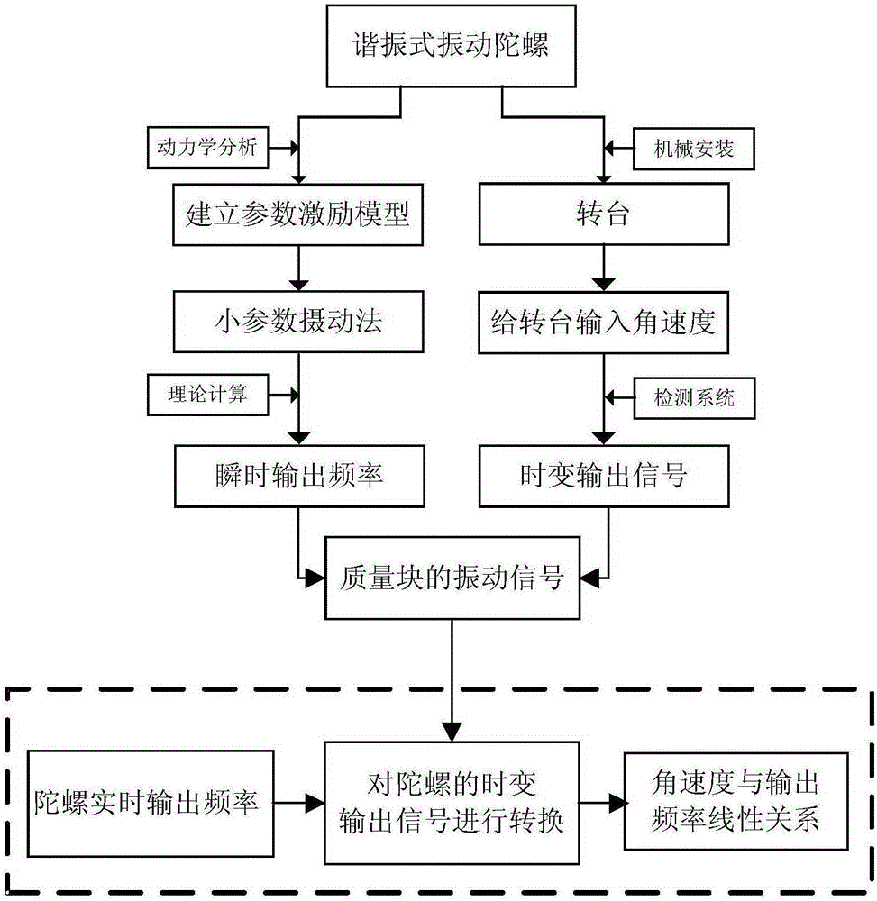
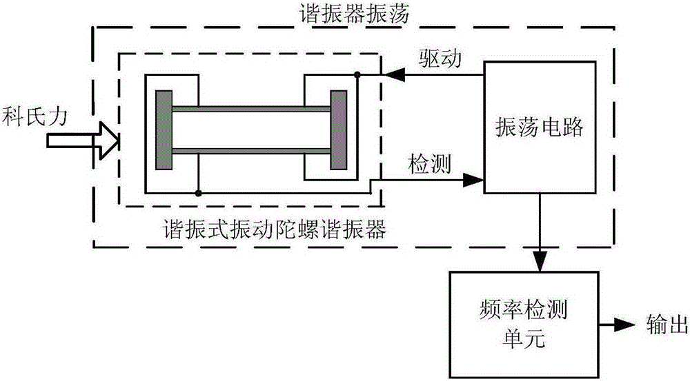
[0031] The present invention comprises the following four basic steps: (1) establishing the dynamic model of the resonant vibrating gyro; (2) obtaining the instantaneous output frequency of the resonant vibrating gyroscope; (3) establishing the output frequency detection system of the resonant vibrating gyroscope; 4) Calculation of the output frequency signal of the resonant vibrating gyroscope. The coefficients of the dynamic model of the resonant vibrating gyroscope are fast-varying functions of time, and the vibration caused by parameter changes is called the parameter excitation characteristic equation. The output frequency detection method of the resonant vibrating gyroscope is based on its dynamic model, using the small parameter perturbation method to obtain the instantaneous output frequency expression; the output frequency detection system of the resonant vibrating gyroscope is established to obtain the time-varying output signal of the gyroscope, and the resonance Th...


PUM


Abstract

An output frequency detection method of a resonant mode vibrating gyro basically comprises the following four steps: (1) building a dynamical model of the resonant mode vibrating gyro; (2) acquiring the instance output frequency of the resonant mode vibrating gyro; (3) building an output frequency detection system of the resonant mode vibrating gyro; (4) calculating an output frequency signal of the resonant mode vibrating gyro. The coefficient of the dynamical model of the resonant mode vibrating gyro is the quick-change function of time, the vibration caused by parametric variation is called as a parametric excitation characteristic equation. The output frequency detection method of the resonant mode vibrating gyro uses a small parameter perturbation method to obtain an instance output frequency expression of the resonant mode vibrating gyro according to the dynamical model of the resonant mode vibrating gyro; the output frequency detection system of the resonant mode vibrating gyro is built to obtain a time varying output signal, and a vibration signal of a mass block in a resonant mode vibrating gyro structure is taken as a conversion condition, so as to arrive at the aims of calculating the frequency signal. According to the output frequency detection method of the resonant mode vibrating gyro, the liner output of the resonant mode vibrating gyro is realized, and the application range of the resonant mode vibrating gyro is expanded.

Description

technical field [0001] The invention belongs to the field of inertial technology, relates to a resonant vibrating gyroscope, in particular to a method for detecting the output frequency of a resonant vibrating gyroscope with direct frequency output, which is suitable for medium and low-precision low-cost navigation systems and positioning and orientation systems. Background technique [0002] The resonant vibrating gyroscope uses the principle of resonance as the detection mechanism of the gyroscope. This kind of gyroscope directly detects the change of the resonant frequency of the resonator to detect the angular velocity, because the frequency signal is a digital signal, the anti-interference ability is strong, and the signal processing is convenient, and there is no need to connect the A / D converter, so it solves its own anti-interference and measurement accuracy. The problem. At present, there are not many researches on resonant vibrating gyroscopes. The main reason is ...

Claims


Application Information

Patent Timeline
Patent Type & Authority Applications(China)
IPC IPC(8): G01C25/00G01C19/56
CPCG01C19/56G01C25/00
Inventor 李艳瞿圆媛李庆玲
Owner CHINA UNIV OF MINING & TECH (BEIJING)
Why Eureka
Try Eureka