Straight pipe air tightness testing equipment
An air tightness test and equipment technology, which is applied in the direction of using liquid/vacuum degree for liquid tightness measurement and measuring the fluid's acceleration and deceleration rate. Sealing and other issues
- Summary
- Abstract
- Description
- Claims
- Application Information
AI Technical Summary
Problems solved by technology
Method used
Image
Examples
Embodiment 1
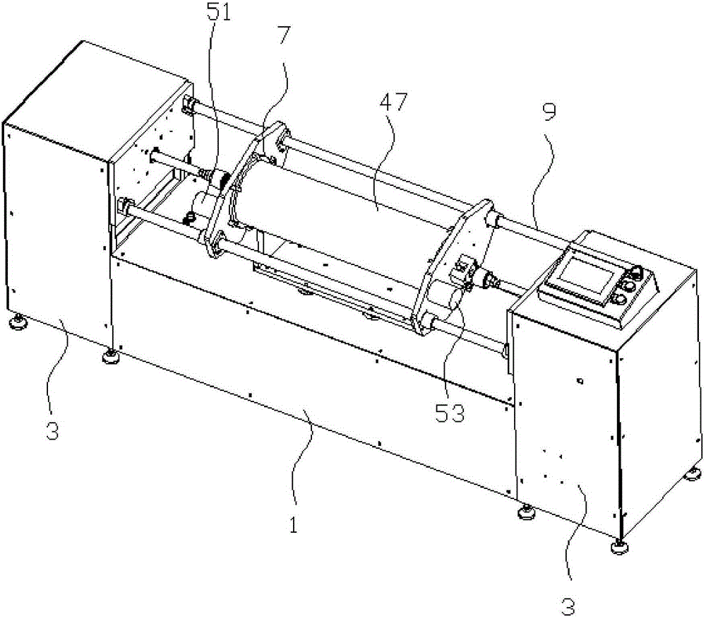
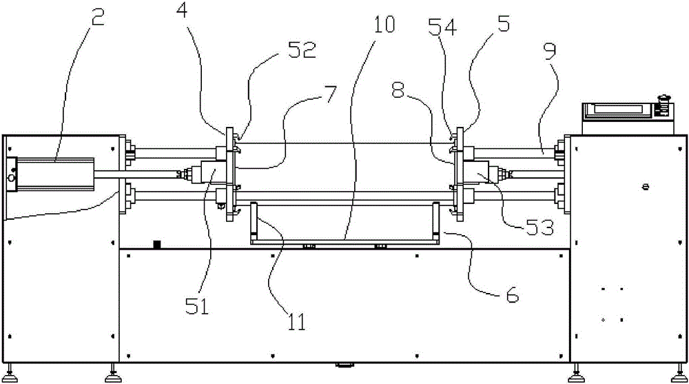
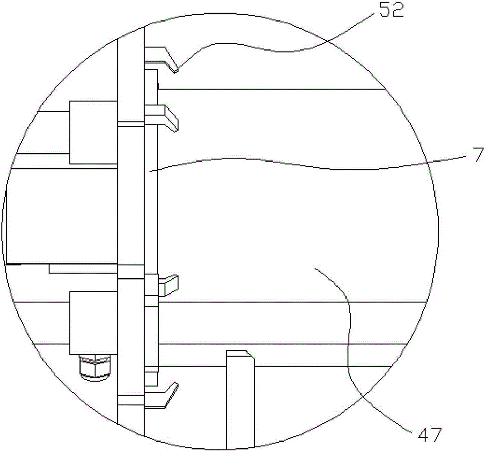
[0040] Example 1: Such as Figure 1 to Figure 5 In the embodiment shown, a straight pipe air tightness test equipment includes an air supply pump, an air pressure sensor 14, a main frame 1, two push plate cylinders 2, two side frames 3 with opposite inner sides, and a main end cover 4. The secondary end cover 5, the main end cover and the secondary end cover are parallel to each other, the main frame is provided with a pipe support frame 6 for supporting the tested pipe, and two push plate cylinders are respectively arranged on two sides On the frame, the piston rod of one of the push plate cylinders is connected with the main end cover, and the piston rod of the other push plate cylinder is connected with the auxiliary end cover. The main end cover is provided with a side surface near the pipe support frame. The main elastic sealing ring gasket 7 contacting the tube end of the pipe under test, the surface of the secondary end cover near the pipe support frame is provided with a...
Embodiment 2
[0044] Example 2: Such as Figure 6 to Figure 8 In the illustrated embodiment, a straight pipe air tightness test equipment includes an air supply pump 13, an air pressure sensor, a main frame, two push plate cylinders, two side frames with opposite inner sides, a main end cover, and a secondary end The main end cover and the auxiliary end cover are parallel to each other, the main frame is provided with a pipe fitting support frame for supporting the pipe under test, and two push plate cylinders are respectively arranged on two side frames, one of which is The piston rod of the push plate cylinder is connected with the main end cover, and the piston rod of the other push plate cylinder is connected with the auxiliary end cover. The surface of the main end cover near the pipe support frame is provided with a surface for contacting the pipe end of the pipe under test. The main elastic sealing ring gasket 7, the surface of the secondary end cover close to the pipe support frame is...
Embodiment 3
[0052] Example 3: The basic structure and implementation of this example are the same as Example 2, the difference lies in that Figure 9 to Figure 12 Shown in: It also includes two anti-return cylinders 31, one of which is fixed on the main end cover by an anti-return bracket 32, and the other anti-return cylinder is fixed on the secondary end cover by an anti-return bracket , The anti-return cylinder is provided with a push plate piston 33 that can slide up and down in the anti-return cylinder, the push plate piston is connected to the inner end of a connecting plate piston rod 34, and the outer end of the connecting plate piston rod is provided There is a suction cup 35, the disc connecting piston rod is vertical, and the push plate piston divides the anti-return cylinder where it is located into an inflatable cavity 36 and a movable cavity 37, and the inflatable cavity is connected to an anti-return air pipe 50 The airing end.
[0053] When the air pressure in the pipe is hi...
PUM
 Abstract
Description
Claims
Application Information
 - R&D
- Intellectual Property
- Life Sciences
- Materials
- Tech Scout
- Unparalleled Data Quality
- Higher Quality Content
- 60% Fewer Hallucinations
Browse by: Latest US Patents, China's latest patents, Technical Efficacy Thesaurus, Application Domain, Technology Topic, Popular Technical Reports.
© 2025 PatSnap. All rights reserved.Legal|Privacy policy|Modern Slavery Act Transparency Statement|Sitemap|About US| Contact US: help@patsnap.com


