an electric push rod

An electric push rod and push rod technology, which is applied in the direction of electric components, electrical components, electromechanical devices, etc., can solve the problems of high cost and easy damage of push rods, and achieve the effect of good positioning effect, avoiding loss and low requirements.

Active Publication Date: 2017-08-01
CHANGZHOU KAIDI ELECTRICAL INC
View PDF7 Cites 1 Cited by
  • Summary
  • Abstract
  • Description
  • Claims
  • Application Information

AI Technical Summary

Problems solved by technology

[0005] The technical problem to be solved by the present invention is to provide another electric push rod with self-locking function to overcome the problems of high cost and easy damage of the existing push rod

Method used


Image

  • an electric push rod
  • an electric push rod
  • an electric push rod

Examples


Embodiment Construction

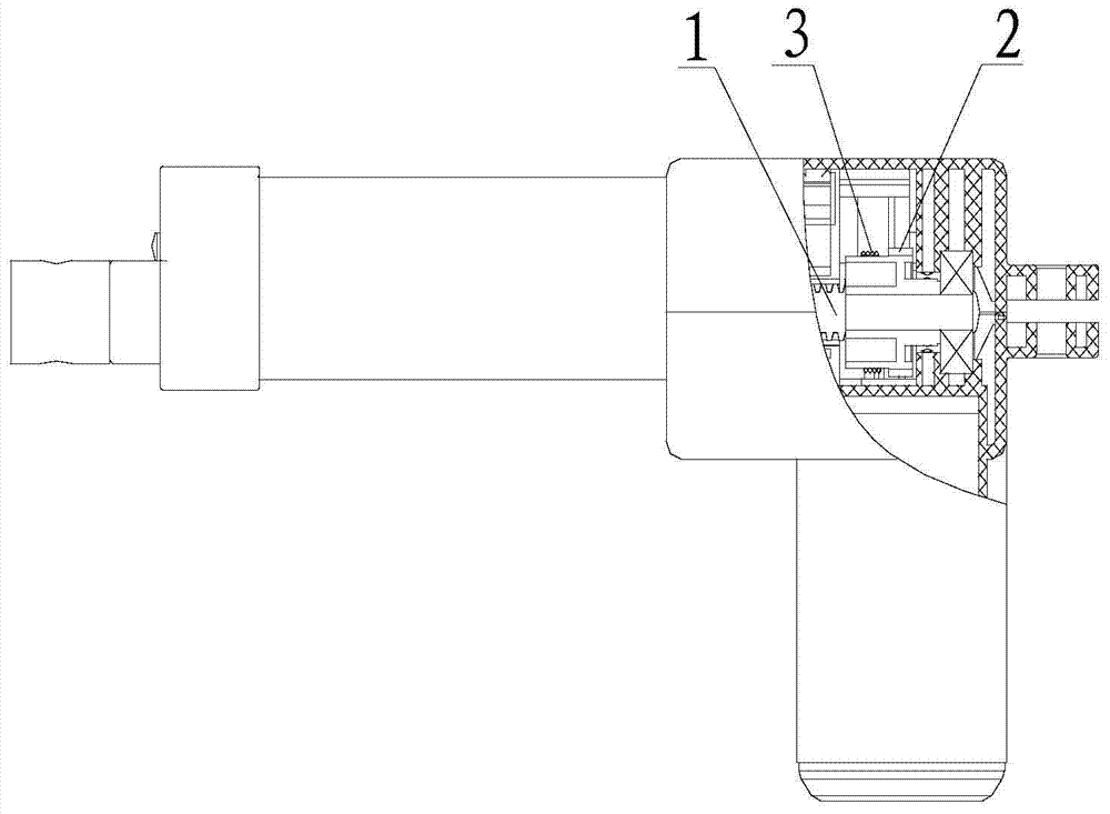
[0027] attached figure 2 It shows a structure diagram in which a damping device acting on the output shaft 4 is provided at the rear end of the output shaft 4 on the motor, and is arranged between the motor coil and the rear support bearing, which embodies the first implementation of the present invention Way.

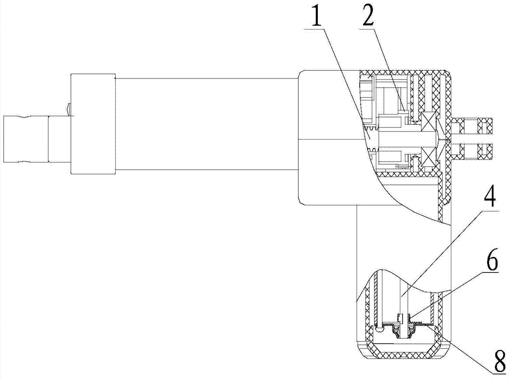
[0028] For the second mode of the structure in which the damping device is installed on the protruding part of the output shaft 4 from the rear end cover 8 of the motor, see the attached Figure 6 , the third way to install it on the front end of the output shaft 4 is shown in the attached Figure 7 , The latter two ways are mainly different in position and an outer cover is added as required, and the stopper 7 in the damping device is arranged on the non-rotating parts of the motor according to the situation.

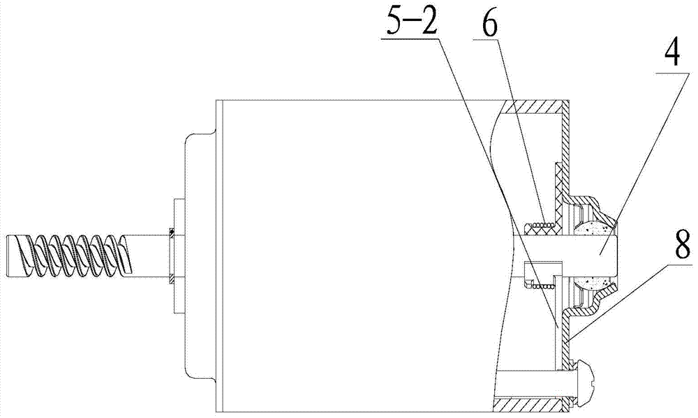
[0029] attached image 3 combined with Figure 4 And attached Figure 5 It shows that the structure of the damping device includes two friction shoes 5 h...


PUM


Abstract

The invention relates to an electric drive device applied to a lifting table, a lifting chair, a lifting bed and the like, in particular to an electric push rod, and aims to solve the problems that an existing electric push rod with a big lead and a self-locking function is high in cost, prone to being damaged and the like. According to the scheme, a motor output shaft of the electric push rod is provided with a damping device for acting on the output shaft, the damping device comprises two or more friction shoes arranged on the output shaft in a holding mode, the outer rings of the friction shoes are sleeved with a spiral spring for tightly holding friction shoes onto the output shaft, the two axial ends of each friction shoe are provided with anti-falling bosses for preventing the spiral spring from falling off, one or more anti-falling bosses are radially extended into rotation stopping fins, the rotation stop fins are blocked by a blocking block on a motor shell for preventing the friction shoes from rotating along with the output shaft, and the inner walls, in contact with the output shaft, of the friction shoes are provided with axial oil storage grooves.

Description

technical field [0001] The invention relates to an electric drive device applied to lift tables, lift chairs, lift beds, etc., in particular to an electric push rod. Background technique [0002] The electric push rod is an electric linear propulsion device used according to the needs of lifting tables, chairs and beds. The general structure is that the output end of the motor output shaft is made of a worm, and the worm gear meshing with the worm is set on the long screw. The screw is covered with a nut that is prevented from rotating, so that the high-speed rotation of the motor is converted into a relatively low-speed linear movement of the nut, and the push rod (or slider) is connected to the nut or made into one piece as a part of the output motion. . [0003] This kind of electric push rod often needs to have a self-locking function during use. For example, the desktop can stop at any height during the process of being raised. The self-locking angle and / or the helix ...

Claims


Application Information

Patent Timeline
Patent Type & Authority Patents(China)
IPC IPC(8): H02K7/06H02K7/102
Inventor 姚步堂李清珍
Owner CHANGZHOU KAIDI ELECTRICAL INC
Why Eureka
Try Eureka