Unlock instant, AI-driven research and patent intelligence for your innovation.

PWM dimming circuit for LED lamp

A dimming circuit and LED lamp technology, which is applied in the direction of electric lamp circuit layout, light source, electric light source, etc., can solve the problems of poor dimming accuracy, affecting the accuracy of current regulation, consumption, etc.

Active Publication Date: 2015-12-30
SUZHOU OPPLE LIGHTING +1
View PDF4 Cites 0 Cited by
  • Summary
  • Abstract
  • Description
  • Claims
  • Application Information

AI Technical Summary

Problems solved by technology

[0003] However, although the control method of the PWM dimming circuit in the prior art is simple and easy to control, its dimming accuracy is poor, especially when the LED load is at low brightness, its current has a large number of ripples, which affects the accuracy of current regulation
[0004] In this regard, some dimming circuits also have constant current control circuits. Specifically, switching elements are used to stabilize the current. However, due to the current and energy consumed by the switching elements themselves, the effect on improving accuracy is general.

Method used


Image

  • PWM dimming circuit for LED lamp
  • PWM dimming circuit for LED lamp
  • PWM dimming circuit for LED lamp

Examples


Embodiment Construction

[0022] The advantages of the present invention will be further elaborated below in conjunction with the accompanying drawings and specific embodiments.

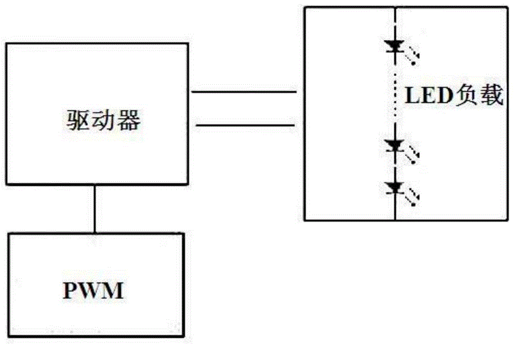
[0023] refer to figure 2 , is a circuit block diagram of the PWM dimming circuit in an embodiment of the present invention. The dimming circuit includes an LED load, a constant current control circuit and a PWM signal generator. The constant current control circuit is connected between the PWM signal generator and the LED load to control the constant current of the LED load to a certain extent, but its constant effect is not the best as described above, and there is still room for further improvement of the constant current effect. space. The constant current control circuit includes a switch element, and the switch element may be a thyristor, a triode and other electronic components that turn on or off the circuit. In one embodiment, the switch element includes a regulator transistor Q1, the base of the regulator transis...


PUM


Abstract

The invention discloses a PWM dimming circuit for an LED lamp. The PWM dimming circuit comprises an LED load, a constant control circuit, and a PWM signal generator, the PWM signal generator is connected with a constant current control circuit, the constant current control circuit comprises a switch element connected with one terminal of the LED load and used for controlling the current of the LED load, when the PWM signal generator generates high-level signals, the switch element is turned on, the constant current control circuit also comprises a feedback circuit connected between a base electrode and an emitter electrode of the switch element, and a voltage drop of the switch element is fed back to the switch element so that the current of the switch element is constant and the current of the LED load is constant. By employing the technical scheme, the current of the LED load in the PWM diming circuit can be controlled with higher precision, and the adjustment of the brightness of the LED is more accurate.

Description

technical field [0001] The invention relates to the field of control circuits for lighting fixtures, in particular to a PWM dimming circuit for LED lamps. Background technique [0002] refer to figure 1 , which is a circuit schematic diagram of a dimming circuit in a commonly used LED lamp at present. In this circuit, the driver controls the LED load current to remain unchanged, and the PWM signal generator sends a PWM signal to control the LED driver, thereby changing the duty cycle of the PWM and then changing LED current. Therefore, by changing the duty cycle, the LED current changes linearly or tends to change linearly. [0003] However, although the control method of the PWM dimming circuit in the prior art is simple and easy to control, its dimming accuracy is poor, especially when the LED load is at low brightness, its current has a lot of ripples, which affects the accuracy of current regulation. [0004] In this regard, some dimming circuits also have constant cu...

Claims


Application Information

Patent Timeline
IPC IPC(8): H05B37/02
Inventor 余世伟左壮朱元陈亮
Owner SUZHOU OPPLE LIGHTING
Features
  • R&D
  • Intellectual Property
  • Life Sciences
  • Materials
  • Tech Scout
  • Unparalleled Data Quality
  • Higher Quality Content
  • 60% Fewer Hallucinations
Learn More