Combined type ice skate bracket
A kind of skate shoes, composite technology, applied in the direction of skates, skating parts, sports accessories, etc., can solve the problems of small elastic deformation of the bracket, increase in the cost of skate shoes, increase in manufacturing costs, etc., to achieve increased cushioning and energy storage effects, The effect of reducing material cost and low cost
- Summary
- Abstract
- Description
- Claims
- Application Information
AI Technical Summary
Problems solved by technology
Method used
Image
Examples
Embodiment 1
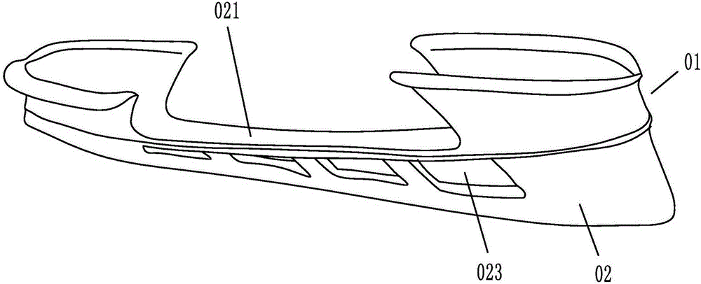
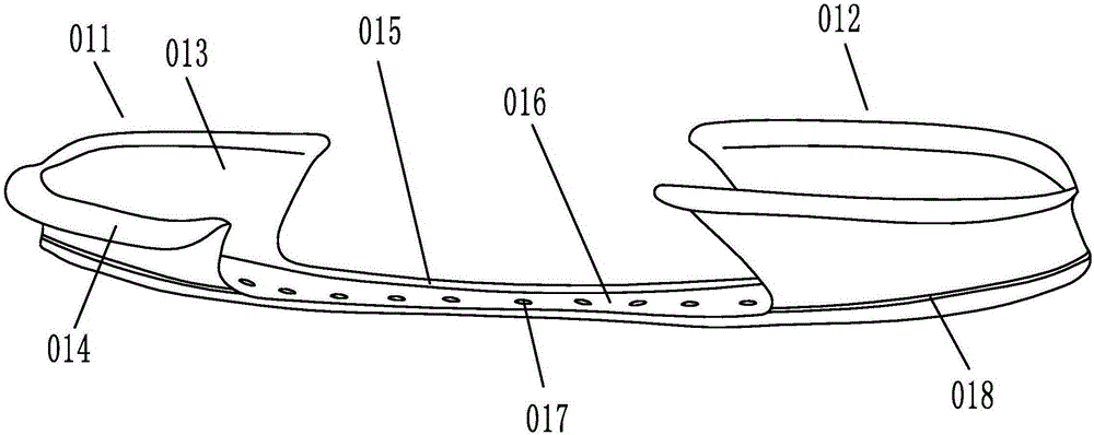
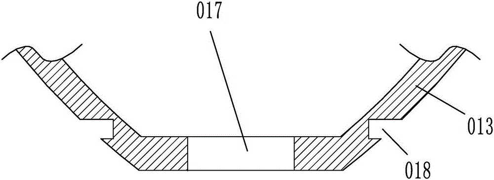
[0023] Embodiment 1: as figure 1 , 2As shown, a composite skate shoe bracket includes a bracket body, the bracket body includes a shoe rack 01 and a blade holder 02, and several weight-reducing grooves 023 are distributed laterally on the blade holder. The shoe rack includes the toe support seat 011, the heel support seat 012 and the connecting strip 015 used to connect the toe support seat and the heel support seat. It is in the shape of "concave". The inner bottom surface of the shoe rack is a storage tank 016, and several connection holes 017 are arranged at intervals at the bottom of the storage tank. Both the toe support seat and the heel support seat include a frame plate 013 connected to the side extension of the connecting bar, and a connecting ear 014 arranged laterally around the edge of the frame plate, such as image 3 , 4 As shown, a connecting groove 018 is arranged transversely at the bottom of the outer surface of the frame plate, and the connecting groove i...
Embodiment 2
[0025] Embodiment 2: The structure of this embodiment is basically the same as that of Embodiment 1, the difference is that, as Figure 5 , 6 As shown in , 7, connecting sleeves 03 are arranged in the connecting holes, and connecting sleeves are arranged in some connecting holes, and the connecting sleeves are distributed in the connecting holes at intervals. The connection sleeve includes a column sleeve 031 and a sleeve head 032 with a diameter larger than the column sleeve. The column sleeve is located in the connecting hole, the sleeve head is located in the accommodation groove, and the support rib 033 is arranged in the column sleeve. The cross section of the support rib is in the shape of a "cross". The longitudinal section of the sleeve is "I" shape, the cross section of the sleeve is square, and the connecting hole is a threaded hole.
[0026] A connecting sleeve is arranged in the connecting hole, and the connecting sleeve includes a column sleeve and a sleeve head ...
PUM
 Abstract
Description
Claims
Application Information
 - R&D
- Intellectual Property
- Life Sciences
- Materials
- Tech Scout
- Unparalleled Data Quality
- Higher Quality Content
- 60% Fewer Hallucinations
Browse by: Latest US Patents, China's latest patents, Technical Efficacy Thesaurus, Application Domain, Technology Topic, Popular Technical Reports.
© 2025 PatSnap. All rights reserved.Legal|Privacy policy|Modern Slavery Act Transparency Statement|Sitemap|About US| Contact US: help@patsnap.com


