
Dust collector suitable for high-temperature dusty tail gas recovery

A tail gas recovery and dust removal device technology, which is applied in the direction of combined devices, dispersed particle separation, chemical instruments and methods, etc., can solve the problems of dust collectors occupying more ground and space, increasing mechanical costs, and waste of fertilizer resources, etc., to achieve Improve heat exchange efficiency, improve dust removal efficiency, increase the effect of contact time

Active Publication Date: 2016-01-06
广州迪斯环保设备工程有限公司
View PDF7 Cites 4 Cited by
  • Summary
  • Abstract
  • Description
  • Claims
  • Application Information

AI Technical Summary

Problems solved by technology

[0002] In the process of fertilizer processing, the drying gas will become high-temperature dusty tail gas after drying treatment. Improper treatment will cause waste and environmental pollution. Generally, cyclone dust collectors are used in industry. Its structure is simple and easy to use. It uses centrifugal force to remove dust The spiral motion in the device is used to separate the dust with a particle diameter greater than 10 μm in the dust-containing gas. Generally, the larger the cylinder body and the cone structure of the cyclone dust collector, the larger the movement path of the gas in the dust collector, and the higher the dust removal efficiency will be. , but it will cause the dust collector to occupy more ground and space, increase the mechanical cost, and increase the wear surface of the body, and the cyclone dust collector cannot separate the dust with a particle diameter of less than 10 μm, and cannot perform heat exchange on high-temperature gas to recover heat
During the processing of general fertilizers, the cyclone dust collector used only has a dust removal rate of about 80%, and a large amount of dust is still discharged into the atmosphere with the tail gas, causing environmental pollution and waste of fertilizer resources.
In addition, when the tail gas of the cyclone dust collector is discharged from the upper part, it will generally contact the tail gas with high dust content, which will cause the purified tail gas to take away part of the tail gas to be dusted when it is discharged outside the cyclone dust collector, thereby reducing the dust removal efficiency.

Method used


Image

  • Dust collector suitable for high-temperature dusty tail gas recovery
  • Dust collector suitable for high-temperature dusty tail gas recovery
  • Dust collector suitable for high-temperature dusty tail gas recovery

Examples


Embodiment Construction

[0038] The present invention will be further described in detail below in conjunction with the accompanying drawings, so that those skilled in the art can implement it with reference to the description.

[0039] It should be noted that the experimental methods described in the following embodiments, unless otherwise specified, are conventional methods, and the reagents and materials, if not otherwise specified, can be obtained from commercial sources; in the description of the present invention, The terms "landscape", "portrait", "top", "bottom", "front", "rear", "left", "right", "vertical", "horizontal", "top", "bottom", The orientation or positional relationship indicated by "inner", "outer", etc. is based on the orientation or positional relationship shown in the drawings, which is only for the convenience of describing the present invention and simplifying the description, and does not indicate or imply that the referred device or element must have Certain orientations, co...


PUM


Abstract

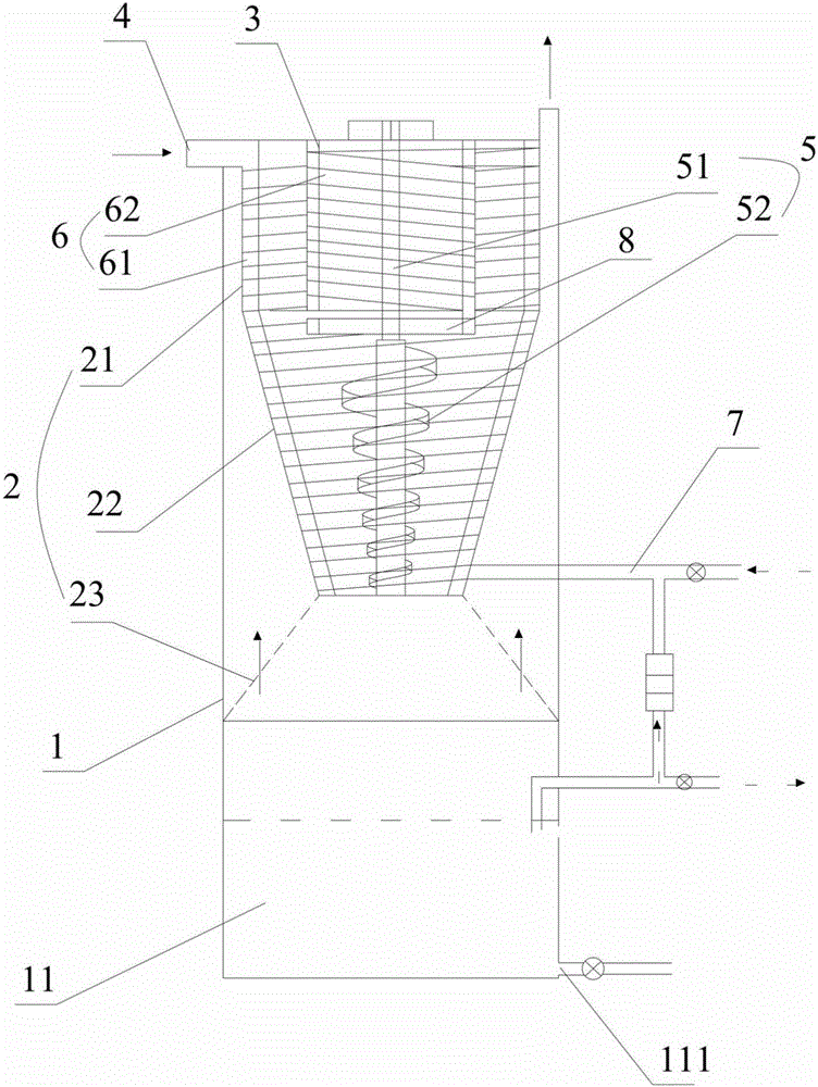
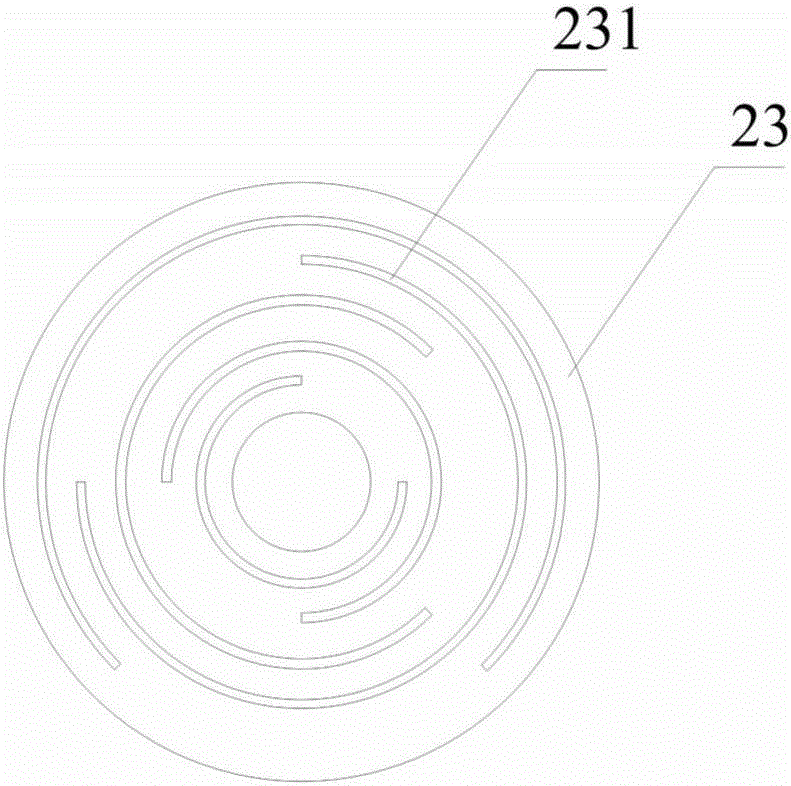
The invention discloses a dust collector suitable for high-temperature dusty tail gas recovery. The dust collector comprises an outer cylinder, a first hollow inner cylinder, a second hollow inner cylinder, an air inlet pipe, a spiral stirring device, a spiral disc, an outer-layer heat exchange pipe, an inner-layer heat exchange pipe and a spraying device, wherein the first hollow inner cylinder is arranged inside the outer cylinder, and is sequentially provided with a first part, a second part and a third part from top to bottom, a first interlayer is formed by the first part and the outer cylinder, and the first part is communicated with the outside; the second part is conical; the third part is shaped like an inverted cone, the lower end of the third part props against the inner wall of the outer cylinder so as to form a second interlayer together with the second part and the outer cylinder, and the third part is provided with a plurality of arc-shaped air discharging holes; the second hollow inner cylinder is arranged inside the first hollow inner cylinder; one end of the air inlet pipe tangentially penetrates through the first part, and the other end of the air inlet pipe is communicated with the outside; the spiral stirring device comprises a rotary shaft; the spiral disc spirally extends along the other end of the rotating shaft; the outer-layer heat exchange pipe winds to the upper part of the first part along the second part, and the lower end of the outer-layer heat exchange pipe is communicated with a liquid inlet pipe; and the inner-layer heat exchange pipe winds along the second hollow inner cylinder, and the upper end of the inner-layer heat exchange pipe is communicated with the outer-layer heat exchange pipe. The dust collector disclosed by the invention has high efficiency.

Description

technical field [0001] The invention relates to the field of high-temperature tail gas treatment. More specifically, the invention relates to a dust removal device suitable for recovery of high-temperature dust-laden tail gas. Background technique [0002] In the process of fertilizer processing, the drying gas will become high-temperature dusty tail gas after drying treatment. Improper treatment will cause waste and environmental pollution. Generally, cyclone dust collectors are used in industry. Its structure is simple and easy to use. It uses centrifugal force to remove dust The spiral motion in the device is used to separate the dust with a particle diameter greater than 10 μm in the dust-containing gas. Generally, the larger the cylinder body and the cone structure of the cyclone dust collector, the larger the movement path of the gas in the dust collector, and the higher the dust removal efficiency will be. , but it will cause the dust collector to occupy more ground ...

Claims


Application Information

Patent Timeline
Patent Type & Authority Applications(China)
IPC IPC(8): B01D50/00
Inventor 张继金
Owner 广州迪斯环保设备工程有限公司
Learn More