
Dehumidifying device and dehumidifying module

A technology of dehumidification part and humidity, applied in the field of dehumidification components, can solve the problem of large-scale dehumidification device and so on

Active Publication Date: 2016-01-06
NABLESCO CORP
View PDF6 Cites 2 Cited by
  • Summary
  • Abstract
  • Description
  • Claims
  • Application Information

AI Technical Summary

Problems solved by technology

However, in this case, the dehumidification unit becomes unnecessarily large

Method used


Image

  • Dehumidifying device and dehumidifying module
  • Dehumidifying device and dehumidifying module
  • Dehumidifying device and dehumidifying module

Examples


Embodiment Construction

[0016] An exemplary dehumidifier will be described with reference to the drawings. In the following description, a dehumidifier is used to dehumidify compressed air used in rail vehicles. However, dehumidifiers can also be used for other purposes. The principle of the dehumidification device described below is not limited to a specific use of the dehumidification device.

[0017] [the whole frame]

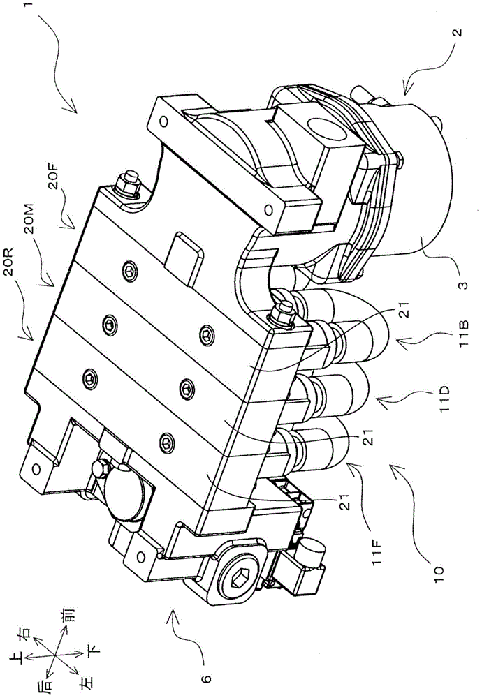
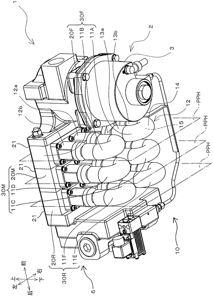
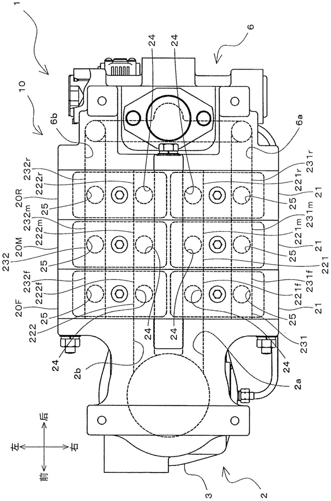
[0018] figure 1 and figure 2 It is a schematic perspective view of the illustrated dehumidifier 1 . figure 1 Mainly the upper part of the dehumidification device 1 is shown. figure 2 Mainly the lower part of the dehumidification device 1 is shown. image 3 It is a schematic plan view of the dehumidifier 1 . Figure 4 yes image 3 It is a schematic enlarged view around the dehumidification unit 10 of the dehumidification apparatus 1 shown. Figure 5 It is a schematic right side view of the dehumidifier 1 . Figure 5 Some components of the dehumidification device 1 shown ...


PUM


Abstract

The present application discloses a dehumidifying device including a base configured to define an inlet channel for first air flow, and an outlet channel for second air flow less humid than the first; and a first dehumidifier including a first inlet and outlet in communication with the inlet and outlet channel, and configured to dehumidify the first air between the first inlet and the first outlet to generate the second air. The base includes a first base portion configured to define first inlet and outlet regions for the first and second air flows; and a second base portion configured to define second inlet and outlet regions in communication with the first inlet and outlet regions. The first and second inlet regions form at least a part of the inlet channel. The first and second outlet regions form at least a part of the outlet channel.

Description

technical field [0001] The invention relates to a dehumidification device for dehumidifying air and a dehumidification assembly used in the dehumidification device. Background technique [0002] Japanese Utility Model Registration No. 3150077 (hereinafter referred to as Patent Document 1) discloses a dehumidifier for dehumidifying compressed air used to generate braking force for a railway vehicle. According to Patent Document 1, the air compressed by the air compression unit is cooled by the aftercooler. After cooling, the compressed air is dehumidified with a dehumidifier and stored in compressed air tanks. [0003] of Patent Document 1 image 3 A cylindrical dehumidification device is disclosed. The dimensions (length and diameter) of the dehumidifier are set to suit the required dehumidification capacity. If the required performance of the dehumidification device changes, the designer needs to redesign the dehumidification device. This means that the performance dive...

Claims


Application Information

Patent Timeline
Patent Type & Authority Applications(China)
IPC IPC(8): B01D53/26
CPCB61H13/34F24F3/14F24F2003/1435B60T17/004B01D53/268B01D63/04
Inventor 水船徹黑光将高桥亮宫内辰雄
Owner NABLESCO CORP
Learn More