Air exhausting device

A device for generating bubbles and a technology for dispersing air, applied in the directions of dissolution, mixer, chemical instruments and methods, etc., can solve the problems of great influence, difficulty, flying out of the cylinder, etc., to improve efficiency, generate high efficiency, and avoid gas wasteful effect

Inactive Publication Date: 2016-01-06
CHONGQING ZEQINGJU SCI & TECH DEV
View PDF0 Cites 0 Cited by
  • Summary
  • Abstract
  • Description
  • Claims
  • Application Information

AI Technical Summary

Problems solved by technology

[0002] The principle of micro-bubble generation is basically that the gas is turned into bubbles by the impact of the protrusions on the inner wall of the tube against the cutting effect. The entire bubble generation process is carried out in the entire cylinder with a relatively large space. and the size of the bubbles) are greatly affected by the ratio of air and water entering the cylinder, so it is difficult to control the optimal air-water ratio in actual operation, so it is difficult to achieve ideal working efficiency, and in the circular At the center of the cylinder, the protrusions cannot reach, and a lot of air bubbles will fly out of the cylinder from the center of the cylinder without being broken and cut, so the efficiency of generating tiny air bubbles is low
On the other hand, because the bubbles are broken by the impact cutting principle of the protrusions, if the speed of the airflow rising is not controlled too fast, the microorganisms in the water are easily killed by the impact cutting of the protrusions. If the speed is too slow, the impact and cutting force on the air bubbles will be insufficient, and the effectiveness of tiny air bubbles will be greatly reduced

Method used


Image

  • Air exhausting device
  • Air exhausting device
  • Air exhausting device

Examples


Embodiment 1

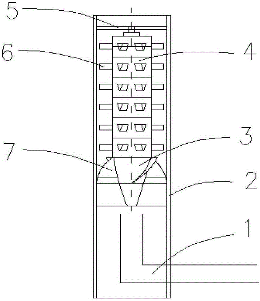
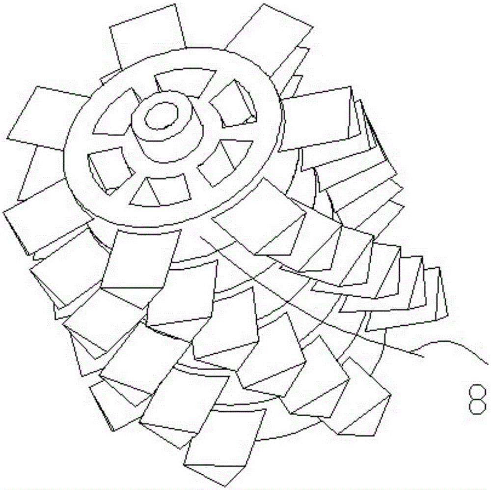
[0018] Such as figure 1 and figure 2 As shown, an air diffuser includes an air intake pipe, an outer cylinder, and an inner core disposed inside the outer cylinder, the inner core is fixedly installed in the outer cylinder and forms a relatively narrow ring-shaped three-dimensional space with the outer cylinder; The upper part of the inner core is formed by stacking six bubble generating devices up and down, and each bubble generating device is surrounded by seven protrusions horizontally in the ring-shaped three-dimensional space. The cross-section of the protrusions is an inverted triangle. The protrusions on the installed bubble generating device are staggered at a 40-degree angle in the vertical direction to form a large air channel. Due to the large air channel, the gas-liquid mixture has a fast flow rate and strong stirring force; the lower part of the inner core is an inverted Conical diversion rotating device, the surface of the diversion rotating device is equipped ...

Embodiment 2

[0020] Such as image 3 As shown, on the basis of Embodiment 1, the upper part of the inner core is changed to be stacked up and down by eight bubble generating devices, and each bubble generating device is provided with eight protrusions horizontally in the ring-shaped three-dimensional space. The cross-section of the object is an inverted triangle, and the protrusions on the bubble generating devices stacked up and down are staggered with each other at an angle of 45 degrees in the vertical direction, forming a narrow air passage much smaller than that of the embodiment on the surface of the inner core. Compared with Example 1, the narrow airway is smaller than the airway, and the gas (big bubble cluster) directly flowing out of the bubble generating device from the narrow airway in this embodiment is much less than that of Example 1. Compared with Example 1 , less gas loss, and higher microbubble generation efficiency.

Embodiment 3

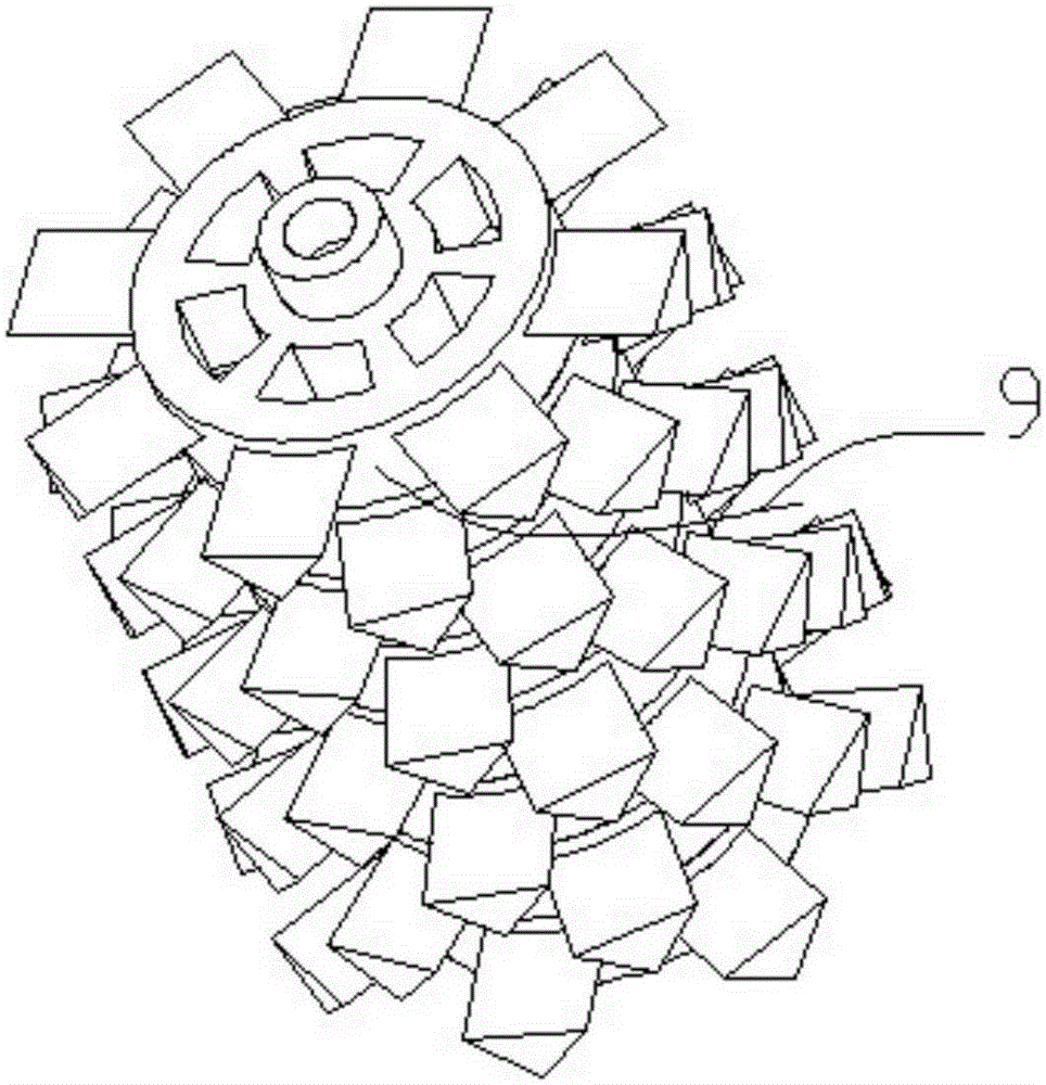
[0022] Such as Figure 4 and Figure 5 As shown, on the basis of Embodiment 1, the upper part of the inner core is replaced with ten bubble generators, and two bubble generators arranged up and down in sequence form a set of variable pressure bubble generators, each group of variable pressure bubble generators In the device, the number of protrusions around the upper air bubble generating device is greater than the number of protrusions on the lower air bubble generating device, the protrusions on the upper and lower stacked air bubble generating devices are staggered from each other, and there is no air channel on the surface of the inner core, Compared with Embodiment 1 and Embodiment 2, the air loss is less, and the generation effect of micro bubbles is better, especially outstanding.


PUM


Abstract

The invention discloses an air exhausting device. The air exhausting device comprises an air inlet pipe, an outer cylinder and an inner core arranged in the outer cylinder; the inner core is installed in the outer cylinder, the upper portion of the inner core is formed by stacking multiple bubble generating devices, the periphery of each bubble generating device is provided with more than six transverse protrusions, and the protrusions on the bubble generating devices which are vertically stacked are stacked together in a mutually staggered mode. According to the air exhausting device, the upper portion of the inner core is composed of the more than six bubble generating devices, the periphery of each bubble generating device is evenly provided with more than six protrusions to form a relatively narrow air channel, and the bubble generating efficiency is high. The other inner core of the air exhausting device is composed of multiple sets of pressure-changing bubble generating devices, the number of the protrusions on the periphery of the bubble generating device located on the upper portion is larger than that of the protrusions on the periphery of the bubble generating device located on the lower portion in each set of the pressure-changing bubble generating devices, the protrusions on the bubble generating devices are mutually staggered, air channels are not formed in the surface of the inner core, therefore, air waste caused by air channel forming is avoided, and the generating efficiency of micro bubbles is improved.

Description

technical field [0001] The invention relates to the technical field of micro-bubble generators, in particular to an air diffuser. Background technique [0002] The principle of micro-bubble generation is basically that the gas is turned into bubbles by the impact of the protrusions on the inner wall of the tube against the cutting effect. The entire bubble generation process is carried out in the entire cylinder with a relatively large space. and the size of the bubbles) are greatly affected by the ratio of air and water entering the cylinder, so it is difficult to control the optimal air-water ratio in actual operation, so it is difficult to achieve ideal working efficiency, and in the circular At the center of the cylinder, the protrusions cannot reach, and a lot of air bubbles will fly out of the cylinder from the center of the cylinder without being broken and cut, so the generation efficiency of tiny air bubbles is low. On the other hand, because the bubbles are broken...

Claims


Application Information

Patent Timeline
IPC IPC(8): B01F3/04B01F5/00
Inventor 常小燕
Owner CHONGQING ZEQINGJU SCI & TECH DEV
Why Eureka
Try Eureka