Full-automatic pipe bending machine

A pipe bending machine, fully automatic technology, applied in the direction of metal processing equipment, feeding device, positioning device, etc., can solve the problems that affect the product qualification rate, low centering efficiency, high labor cost, etc., achieve simple structure, small labor force, Ease of installation

Inactive Publication Date: 2016-01-06
JIANGSU XINSIWEI PHOTOELECTRIC CO LTD
View PDF7 Cites 6 Cited by
  • Summary
  • Abstract
  • Description
  • Claims
  • Application Information

AI Technical Summary

Problems solved by technology

In the actual use process, the stability of the clamping device installation is directly related to the accuracy of the bending angle of the product when the pipe bender performs the pipe bending operation, which directly affects the product qualification rate, and the current overtime fixed pair is Using bolts to lock directly, in actual use, lack of flexibility and insufficient screw hole precision, will directly produce a large number of waste parts, and at the same time, most of the current clamping devices are manually operated, which is time-consuming, labor-intensive, labor-intensive, and efficient. It is low and has high requirements for the technology and proficiency of the pipe bending personnel, high labor cost and large labor force; in the actual production process, most of the pipe bends are middle pipe bends. When bending pipes, if the centering position is not accurate, it is easy to Defective products are produced, and most of the centering steps in the process of bending pipes are manual centering. During the manual centering, it is necessary to draw a ruler and draw a line. Not only is the centering efficiency low, but the accuracy is poor, time-consuming and laborious

Method used


Image

  • Full-automatic pipe bending machine
  • Full-automatic pipe bending machine
  • Full-automatic pipe bending machine

Examples


Embodiment Construction

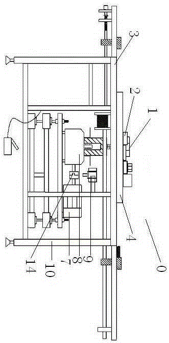
[0033] A fully automatic pipe bending machine, characterized in that, the fully automatic pipe bending machine 0 includes a pipe bending device 1, a clamping device 2 and an automatic centering device 3;

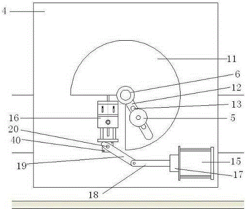
[0034] The pipe bending device 1 includes a panel 4, a movable mold 5, a fixed mold 6, a motor 7, a speed reducer 8 and a brake cylinder 9, the panel 4 is horizontally arranged by a support 10, the panel 4 is square, and there are 3 holes on it. / 4 circle movable mold movement port 11, the fixed mold 6 is fixedly arranged at the center of the 3 / 4 circle shown by the panel 4, and the reducer 8 is arranged at the center of the 3 / 4 circle shown by the panel 4 At the lower end, the output end of the speed reducer 8 is provided with a swing arm 12, the swing arm 12 is elongated, one end of which is fixedly connected with the output end of the speed reducer 8, and the swing arm 12 is provided with a movable mold adjustment port 13. The movable mold 5 is detachably connected to the...


PUM


Abstract

The invention discloses a full-automatic pipe bending machine. The full-automatic pipe bending machine is characterized by comprising a pipe bending device, a clamping device and an automatic aligning device, wherein a telescopic cylinder pushes a connecting rod and drives a regulating rod, so that the tip end of the regulating rod is resisted against a pressure plate of a clamping part, and therefore, a clamping plate of the clamping part clamps a workpiece, the operation is simple and quick, the labor force is small, the labor cost is reduced, and the pipe bending efficiency is also improved; during aligning, an aligning air cylinder drives an optical axis at one side to move; a gear is matched with a rack, so that an optical axis at the other side synchronously and oppositely moves, and then left and right slide paths on side plates at the two sides of the full-automatic pipe bending machine are synchronously aligned, and therefore, the aligning position is accurate, the aligning efficiency is high and manual aligning is completely replaced, the aligning is time-saving and labor-saving, working efficiency of pipe bending is greatly improved, and pipe bending process is optimized; and meanwhile, the full-automatic pipe bending machine is low in manufacturing cost, and production cost is reduced.

Description

technical field [0001] The invention relates to a pipe bending machine, in particular to a fully automatic pipe bending machine. Background technique [0002] Pipe bending machines can be roughly divided into CNC pipe bending machines, hydraulic pipe bending machines and so on. It is mainly used in electric power construction, highway and railway construction, pipeline laying and repairing in boilers, bridges, ships, furniture, decoration, etc. It has the advantages of multiple functions, reasonable structure, and simple operation. In the actual use process, the stability of the clamping device installation is directly related to the accuracy of the bending angle of the product when the pipe bender performs the pipe bending operation, which directly affects the product qualification rate, and then the current overtime fixed pair is Using bolts to lock directly, in actual use, lack of flexibility and insufficient screw hole precision, will directly produce a large number of ...

Claims


Application Information

Patent Timeline
Patent Type & Authority Applications(China)
IPC IPC(8): B21D7/16B21D43/00
Inventor 孟斌
Owner JIANGSU XINSIWEI PHOTOELECTRIC CO LTD
Why Eureka
Try Eureka